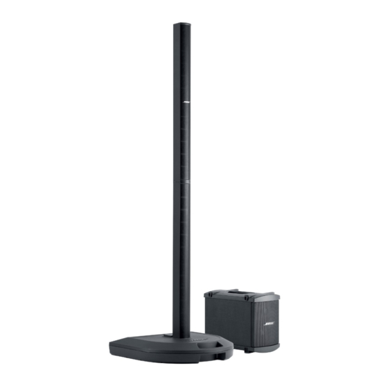
Bose Personalized Amplification System Handbuch zur Fehlersuche - Seite 10
Blättern Sie online oder laden Sie pdf Handbuch zur Fehlersuche für Verstärken Bose Personalized Amplification System herunter. Bose Personalized Amplification System 50 Seiten.
Auch für Bose Personalized Amplification System: Benutzerhandbuch (28 seiten)

Bass module sensing circuitry
On the bass connector, there are four pins. 1+ and 1- outputs bass signal, 2+ and 2- is used to
check the number of bass modules connected to the power stand. When there is no bass
module connected, the resistance value between 2+ and 2- is greater than 10k ohms, when one
bass module is connected to the power stand, the resistance between 2+ and 2- is equal to 10k
ohms, when two bass modules are connected, the resistance value between 2+ and 2- is equal
to 5k ohms, when there are more than two bass loudspeakers, the resistance value between 2+
and 2- is less than 5k ohms. Once the system detects how many, if any bass modules are
connected to the power stand, it will adjust the output level and the EQ accordingly to provide
the proper outputs for that configuration.
System Status LED
On the input panel PCB, there is a three color LED. The different colors of this LED represent
different operating conditions for the power stand.
•
Green: operating normally
•
Green blink fast: updating software or preset
•
Green blink slowly: software update success
•
Red blink slowly: software update failure
•
Orange: power or amplification protection enabled (fault condition)
Codec
In the system, there are five codec ICs: U386 (for Ch1 & Ch2 A/D), U385 (for Ch3 & Ch4 A/D),
U387 (for line & bass D/A) [DSP PCB sheet 1, B/C/D5], U431 (for SPDIF IN) [DSP PCB sheet 2,
D3], U435 (for SPDIF OUT) [DSP PCB sheet 2, B6].
U386, U385, U387, U431, and U435 include the following functions:
•
U386: Two channels of 24-bit ADC, one for Ch1 analog input and one for Ch2 analog input.
The ADC will input signal levels in levels in excess of 2Vrms. Master mode.
•
U385: Two channels of 24-bit ADC, one for Ch1 analog input and one for Ch2 analog input.
The ADC will input signal levels in levels in excess of 2Vrms. Slave mode.
•
U387: Two channels of 24-bit DAC, one for Line analog output and one for Bass analog
output. Maximum output signal level is 2Vrms. Slave mode.
•
U431: Two channels of 24-bit digital audio interface receiver.8:2 S/PDIF Input MUX, AES/
SPDIF input pins selectable in hardware mode.
•
U435: Two channels of 24-bit digital audio transmitter. Output Ch1/Ch2 input signal. Slave
mode.
•
A crystal oscillator which establishes the ADC/DAC/SPDIF OUT sampling rate, in this case,
it is 12.288MHz / 256 = 48KHz.
•
SPDIF IN sampling rate is the same as playing frequency, generally 44.1KHz.
•
U386, U385, U387, U431, U435: Standalone Hardware mode.
•
Word rate clock for the audio data on the SDOUT pin. Frequency will be the sample rate.
•
Serial bit clock for audio data on the SDOUT pin.
•
a serial bit stream containing the 24-bit audio data.
•
U386, U385: 3-wire serial digital output port, U387: 3-wire serial digital input port,
•
U431: 3-wire serial digital output port, U435: 3-wire serial digital input port. I
data output/input these ports.
In addition, the timing of the data flow into and out of the DSP is driven by the codec.
The serial ports on the DSP run asynchronously to the 30MHz clock which drives the
DSP.
THEORY OF OPERATION
10
2
S format digital
