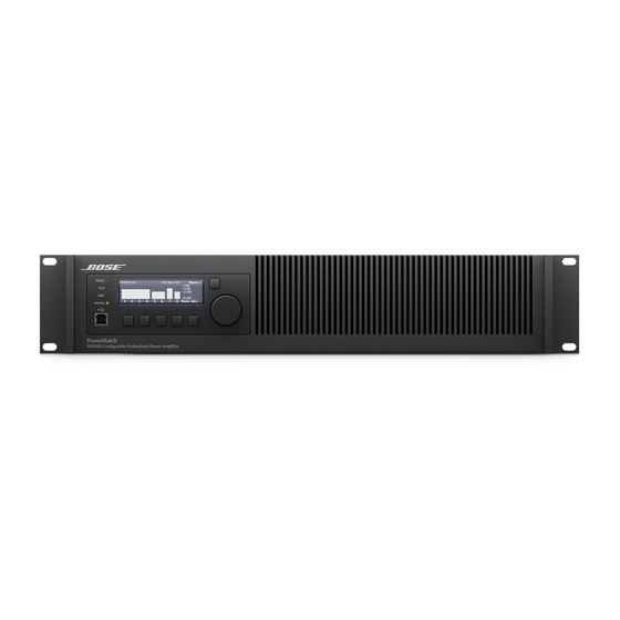
Bose PM8500 Benutzerhandbuch - Seite 34
Blättern Sie online oder laden Sie pdf Benutzerhandbuch für Verstärken Bose PM8500 herunter. Bose PM8500 44 Seiten. Configurable professional power amplifier
Auch für Bose PM8500: Technisches Datenblatt (6 seiten), Installations- und Sicherheitsanweisungen (21 seiten)

User guide
sample output Configurations for Different loudspeaker loads
This table should help you select the appropriate output mode for a given loudspeaker load.
Figure 14. loudspeaker load output configurations
Power Rating (20 - 20 kHz)
THD For Power Rating
Mono Mode: 8 channels (per channel)
V-Bridge Mode: 4 channels (per channel)
I-Share Mode: 4 channels (per channel)
Quad Mode: 2 channels (per channel)
Maximum Rated Power, Total All Channels
Peak Output Voltage (Mono/V-Bridge/Quad modes)
Voltage Gain (Mono/V-bridge/I-Share/Quad modes)
Notes for Power Ratings
For reference, the following two examples illustrate two different output configurations using RoomMatch™ array module loudspeakers.
Front panel configuration settings are provided. While not covered in this documentation, ControlSpace
additional configurability to these examples. Further information on this software can be found on pro.bose.com.
Configuration of a RoomMatch™ Four-Module Array (example 1)
In this example, four full-range RoomMatch array modules are connected to one PowerMatch™ amplifier, arranged as follows:
(2) Bose® RoomMatch 7010 array module loudspeakers (70° H x 10° V)
(2) Bose RoomMatch 12020 array module loudspeakers (120° H x 20° V)
(1) Bose PowerMatch PM8500 configurable professional power amplifier
Figure 15. RoomMatch four-module array configuration
Note: All RoomMatch loudspeaker connections use Neutrik NL4 speakON-type cable connectors. Please refer to RoomMatch
loudspeaker documentation for further details.
Front Panel Configuration Menu Settings:
1. MAiN MeNU < CoNFig < oUTPUT CoNFig
Set the output configuration for channels 1-8 to MONO mode.
2. MAiN MeNU < DsP < sPeAkeR PReseTs
For channels 1, 3, 5, and 7 set SERIES to "RoomMatch" and MODEL to "RM_Array LF."
For channels 2, 4, 6, and 8 set SERIES to "RoomMatch" and MODEL to "RM_Array HF."
3. MAiN MeNU < DsP < ARRAy eQ
For each input channel (A-H) that is routed to an output channel, set the MODULES value to 4 and the V-Angle parameter to
60 degrees, which is the total vertical angle of the four shown modules. Ensure that the state of the Array EQ is toggled to ON.
Page 34 User Guide
2 Ω
4 Ω
<0.1% THD
500 W
500 W
500 W
1000 W
(1)
1000 W
500 W
(1)
1000 W
(1)
2000 W
Configuration not optimal/not recommended
(1)
pro.bose.com
8 Ω
70 V
1% THD
300 W
not available
1000 W
800 W
300 W
not available
(1)
1000 W
(1)
1600 W
4000 W
71 / 142 / 142 V
33 / 36 / 33 / 36 dB
Designer™ software provides
®
100 V
not available
1000 W
not available
2000 W
English
