Bose PM8500 / PM8500N PM8250 Installations- und Sicherheitsanweisungen - Seite 10
Blättern Sie online oder laden Sie pdf Installations- und Sicherheitsanweisungen für Verstärken Bose PM8500 / PM8500N PM8250 herunter. Bose PM8500 / PM8500N PM8250 21 Seiten. Configurable professional power amplifier
Auch für Bose PM8500 / PM8500N PM8250: Technisches Datenblatt (6 seiten)
Installation
Introduction
Thank you for choosing the Bose PowerMatch™ PM8500 Configurable Professional Power Amplifier!
This guide is intended to provide safety warnings, precautions, and basic setup and configuration information for the Bose
PowerMatch™ PM8500 configurable professional amplifier. For more complete operating information, please download the document
PowerMatch PM8500 Operation Manual from the pro.bose.com website. Additional information regarding the use of ControlSpace
software for setup, control, or monitoring may be found in the Help section of the software, which may also be downloaded from
pro.bose.com.
The information furnished in this guide does not include all details of design, production, or variations of the equipment. Nor does it
cover every possible situation which may arise during installation, operation, or maintenance. If you need assistance beyond the scope
of this guide, please contact your local Bose Representative or Technical Support specialist.
Throughout this document, the naming convention "PM8500" refers to both the PM8500 and PM8500N versions, unless stated
otherwise.
Summary Description
The Bose PowerMatch PM8500 and PM8500N are configurable professional audio amplifiers. The two versions are identical except that
the PM8500N version adds an RJ45 connector on the rear panel to allow network control and monitoring of multiple PM8500N units,
using Bose ControlSpace
®
Controls, Displays and Connectors
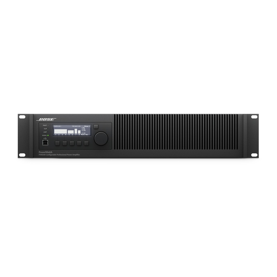
Figure 1. PM8500 and PM8500N Front Panel View
1
8
6
1.
LED Indicators
2.
LCD Display
3.
Navigation Soft Key
B1
4.
Rotary Encoder
Figure 2. PM8500N Front Panel View (PM8500 identical except no RJ-45 network connector)
18
9
9.
Analog Input connectors (A-H)
10.
Fault-Notification Output
11.
Ethernet RJ-45 network connector*
12.
Rear airflow vents
13.
Digital input card slot cover
Page 10
Installation and Safety Guidelines
software and standard Ethernet network equipment.
2
3
5
4
12
11
10
5.
Menu Soft Keys (1-5)
6.
USB connector
7.
Front airflow vents
8.
Front rack-mount ears
13
14.
Output connectors (1-4 and 5-8)
15.
AC Mains receptacle
16.
AC Mains retention clip
17.
Power Switch
18.
Rear rack-mount support tabs
(*PM8500N model only)
7
14
15
16
pro.Bose.com
®
8
18
17
English