Bose Lifestyle 35 Series II Installationshandbuch - Seite 13

Blättern Sie online oder laden Sie pdf Installationshandbuch für Kopfhörer Bose Lifestyle 35 Series II herunter. Bose Lifestyle 35 Series II 42 Seiten. Noise cancelling
Auch für Bose Lifestyle 35 Series II: Installationshandbuch (36 seiten), Benutzerhandbuch (25 seiten), Benutzerhandbuch (24 seiten), Benutzerhandbuch (13 seiten), Handbuch zur Schnelleinrichtung (3 seiten), Betriebshandbuch (46 seiten), Benutzerhandbuch (36 seiten), Benutzerhandbuch (32 seiten), Schnellstart-Handbuch (2 seiten), Werksreset (2 seiten), Schnellstart-Handbuch (2 seiten), Benutzerhandbuch (38 seiten)
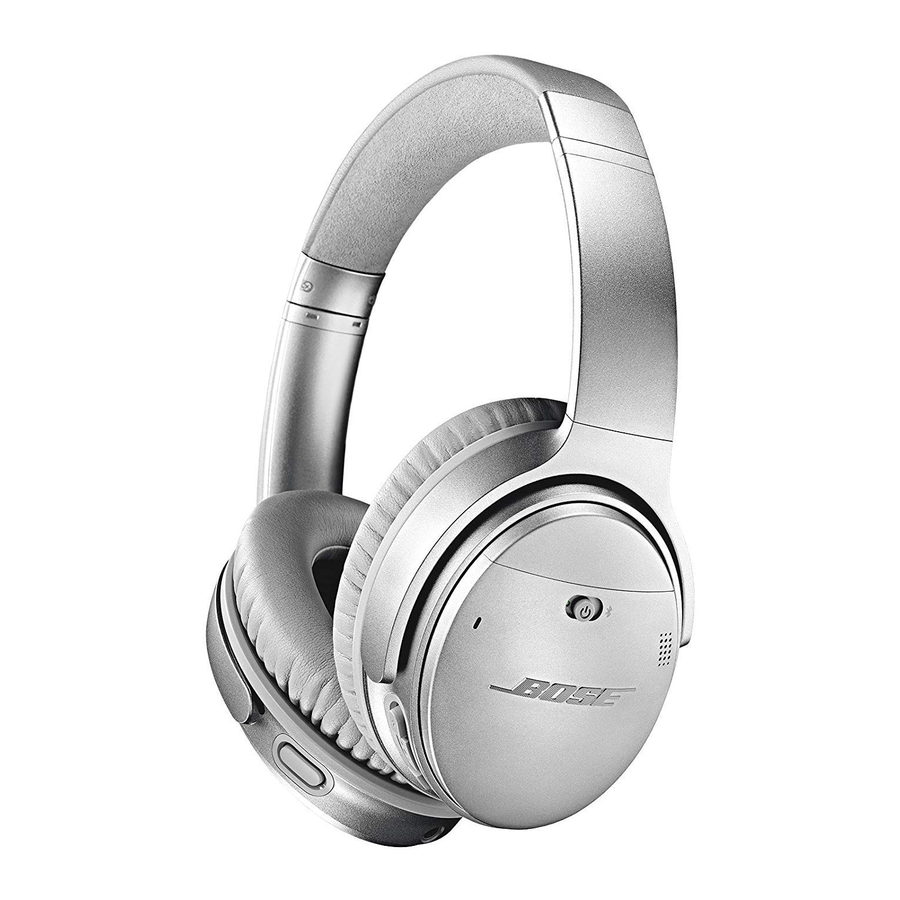
Bose Lifestyle 35 Series II Installationshandbuch
English
Español
Cube array speaker
Cube speaker
Figure 9
Making a two-wire cable
connection
Français

Making two-wire connections for cube or cube array speakers

Notice the marks on each cable wire. The one marked with a red collar is positive (+) and the
plain one is negative (–) to guide you in connecting them to the positive (red) and negative
(black) terminals on the back of each speaker.
1. Match the correct cable to the corresponding speaker location:
• Front speaker cables have blue connectors at one end, with L (left), R (right), or
C (center) molded into the connectors. A red collar on each + wire is labeled LEFT,
RIGHT, or CENTER.
• Surround speaker cables have orange connectors at one end, with L (left) or R (right)
molded into the connectors. A red collar on each + wire is labeled LEFT or RIGHT.
2. Connect the wire end of one speaker cable to the terminals on the rear of the matching
speaker:
• Press the terminal tab on the back of the speaker and insert the red collared wire (+)
into the red terminal and the plain wire ( ) into the black terminal.
• Release the tab to secure the wire. Repeat this step for each of five speakers.
Terminal tab
3. Follow the instructions below to connect each cable to the corresponding jack on the
®
Acoustimass
module.

Connect the cables from each speaker to the module

You may find it convenient to temporarily turn the module upside down while making these
connections. Then, be sure to place the module on its side or bottom surface when the
connections are completed.
• Plug the blue cable connectors marked L and R into the FRONT L and R jacks.
• Plug the blue cable connector marked C into the FRONT C jack.
• Plug the orange cable connectors marked LS and RS into the SURROUND L and R
jacks.
To lengthen speaker cables, as needed, use heavy-duty RCA extension cables or splice in
18-gauge or thicker cord (connecting + to + and – to –).
Note: To purchase extension cable, contact your dealer or electronics store. Or, to contact Bose
directly, refer to the address list provided in the carton. If you prefer, you can order cables from
our website: www.bose.com.
Red
terminal
Left, Right, or Center
printed on the
red collar
B
S
C
ASIC
YSTEM
ONNECTIONS
13