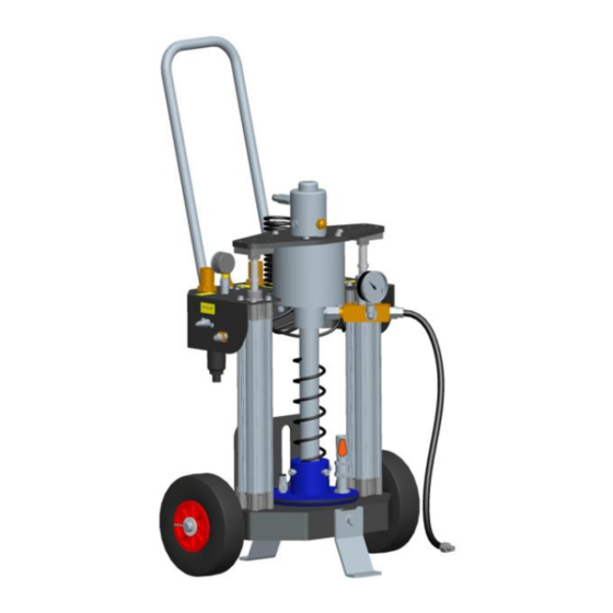
DROPSA 0400606 Benutzer- und Wartungshandbuch - Seite 5
Blättern Sie online oder laden Sie pdf Benutzer- und Wartungshandbuch für Water Pump DROPSA 0400606 herunter. DROPSA 0400606 10 Seiten. Pneumatic pumps trolley mounted

5. UNPACKING AND INSTALLATION
5.1 UNPACKING
Once a suitable installation position has been identified, unpack the product and prepare for installation. It is important to
inspect the product to ensure that there has been no damage during transportation. The packaging material used does not
require any special disposal procedures. You should refer to you regional requirements.
5.2 INSTALLATION
No pump installation operations are required.
6. OPERATING INSTRUCTIONS
6.1 START-UP OF THE PUMP
Before using the product, a few preliminary checks must be performed:
• The unit can be opened and repaired only by specialized personnel.
• Using the pump submerged in fluids or in a particularly aggressive or explosive/flammable environment is prohibited unless
it has been prepared ahead of time by the supplier for this purpose.
• Use gloves and eye protection as required by the sealant safety data sheet.
• DO NOT use lubricants that are aggressive to NBR gaskets. If you are unsure, contact the Dropsa SpA technical office.
• Never ignore health hazards and always follow sanitary regulations.
• Check the integrity of the pump.
• Ensure that all the selector switches (5-7-9) are in the "off" position and that the pressure regulators (6-8) are calibrated to
the minimum.
• The presser cylinders pressure regulator (10) is precalibrated for normal use.
• Ensure that the flow valve (11A) on the manifold valve (11) is open and that the pressure release valve (11B) is closed.
• Connect the pump to the low pressure pneumatic circuit using the quick coupler (3).
• Ensure that the pump is at operating temperature.
• Connect and check the tightness of the outlet fitting (13).
• Connect the earthing cable (14).
6.2 OPERATING PRINCIPLE
The follower plate (1A) built into the pump and inserted in the barrel makes suction easier for the pneumatic pump (1), as
well as guaranteeing complete emptying of the barrel.
Insertion of the follower plate in the full barrel and extraction of the same when the sealant/grease is depleted is achieved
by raising and lowering the unit (1) through pneumatic cylinder controls (2) making up the structure stanchions.
ATTENTION: When introducing the follower plate into the barrel, inserting your hands is strictly prohibited.
6.3 OPERATING INSTRUCTIONS
6.3.1 Cart handling
•
Before moving the pump, rotate the safety foot to the horizontal position (17A). To rotate the foot, push and rotate it
simultaneously.
•
Before carrying out any operation on the pump, return the safety foot (17) to the vertical position.
6.3.2 Installation of the sealant barrel
•
Move the selector switch (9) to the "up" position, raise the pump (1) to a height sufficient for inserting the barrel and then
return the selector switch to "off".
•
Open the air pressure vent valve (16) located on the follower plate.
•
Arrange the barrel on the cart platform.
•
Move the selector switch (9) to the "down" position, lower the pump to the edge of the barrel and then return the selector
switch to "off".
•
Centre the barrel with the follower plate.
•
Move the selector switch (9) to the "down" position and lower the pump until it is in contact with the grease level.
•
Move the rear sheet (15) until it is in contact with the barrel wall. Secure the sheet with the appropriate screws.
•
Move the selector switch (9) to the "off" position.
•
Close the air pressure vent valve (16) located on the follower plate.
6.3.3 Sealant pumping
5
