DROPSA 2487010 Benutzerhandbuch für Betrieb und Wartung - Seite 6
Blättern Sie online oder laden Sie pdf Benutzerhandbuch für Betrieb und Wartung für Water Pump DROPSA 2487010 herunter. DROPSA 2487010 18 Seiten.

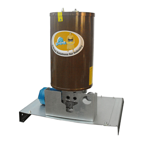
5. MACHINE COMPONENTS
5.1. STANDARD PUMP COMPONENTS
5.1.1 FIXED FLOW RATE PUMPING ELEMENTS
The pump may be configured with two fixed flow rate pumping elements (25 cm^3/ min for each pumping element.
The seal between the piston and pumping element casing is dry, as the insertion of a gasket is not required.
The check valve for the pumping element is has a cone-shaped seal. This solution guarantees optimal system sealing at high
operating pressures (max pressure of 380 bar).
The pumping elements are mounted on the pump casing without the need to disconnect the line pipes with a threaded
connection, which makes assembly/disassembly easier.
2
3
4
Minimum laser level (for grease pump)
1
Maximum level
2
Tank
3
Ratio motor
4
Return
5
Delivery
6
6
1
5
6
STANDARD PUMP COMPONENTS
7
8
9
10
11
12
8
7
By-pass
Pumping system
Pressure gauge
Loading (for grease pump)
Minimum tank level (for oil pump)
Lubricant loading cap (for oil pump)
12
11
10
9
