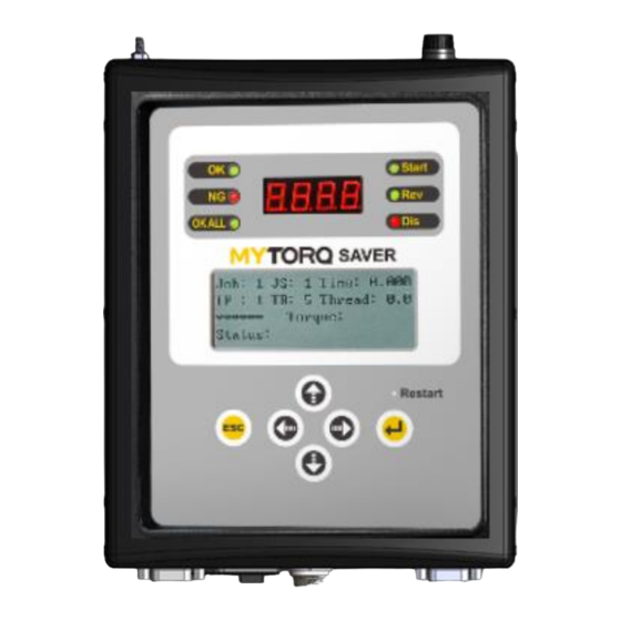
ANLIDAR MYTORQ MY-SAVER Benutzerhandbuch - Seite 11
Blättern Sie online oder laden Sie pdf Benutzerhandbuch für Messgeräte ANLIDAR MYTORQ MY-SAVER herunter. ANLIDAR MYTORQ MY-SAVER 16 Seiten.

GATE function abnormal:When the GATE function is on and
Er
function abnormal, the buzzer will alarm and LCM displays
this Er.
Screwdriver end communication error:When the electric
ES
screwdriver communication error occurs, the
electric screwdriver will be stopped and the LCM displays this ES.
EOC
Calibration is required when EOC is stated on LCM display.
When LCM displays the word ELS, it indicates that the SD card
capacity is less than 100MB, and it will stop the operation of the
ELS
screwdriver. Which need to press the Enter key to release the
screwdriver freeze state.
9. External output control function description
Connector No
Symbol Definition
CN 1
START
CN 2
COM
CN 3
CN 4
CN 5
REVERSE
CN 6
COM
CN 7
OK
CN 8
COM
CN 9
NG
CN 10
COM
CN 11
OKALL
CN 12
COM
CN 13
Vdc
CN 14
GND
RUN FWD:
When the screwdriver is on,CN1、2 short.
When it short, CN1+CN2 short.
When it open, CN1+CN2 open.
-
-
RUN BWD:
When the screwdriver reverse,CN5、6 short.
When it short, CN5+CN6 short.
When it open, CN5+CN6 open.
OK:
When a screw is fastened,CN7、8 short.
When it short, CN7+CN8 short.
When it open, CN7+CN8 open.
NOK:
When there is malfunction,CN9、10 short
When it short, CN9+CN10 short.
When it open, CN9+CN10 open.
OK SEQUNECE:
When it completed sequence setting screw,CN11、12 short.
When it short, CN11+CN12 short.
When it open, CN11+CN12 open.
Controller output voltage: DC+12V/100mA or +24V/50mA
Default value: +24V/50mA (+12V/100mA can be customized).
Output voltage GND
Function Description
10
Please
confirm
phase and setting mode
NA
NA
NA
-
GATE
