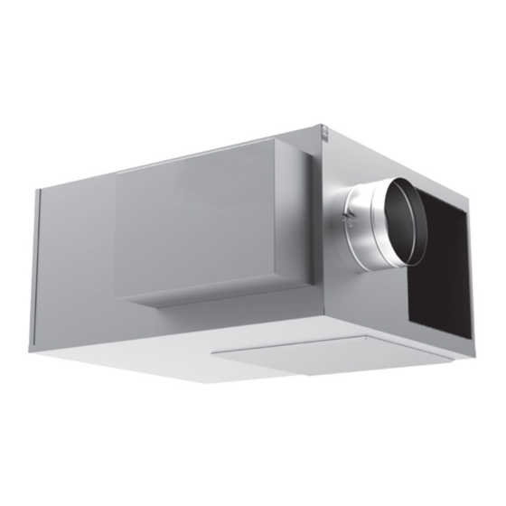
Daikin MQFVI5 Handbuch für Installation und Wartung - Seite 10
Blättern Sie online oder laden Sie pdf Handbuch für Installation und Wartung für Fan Daikin MQFVI5 herunter. Daikin MQFVI5 12 Seiten. Parallel fan powered variable air volume (vav) terminal box

Specific Electric Heat Troubleshooting Procedures:
Electric shock hazard . Can cause personal injury or
equipment damage .
This equipment must be properly grounded. Connections and
service to the MicroTech III Chiller Unit Controller must be
performed only by personnel knowledgeable in the operation
of the equipment being controlled.
Table 1: Electric Heat Troubleshooting Procedures
Possible Cause
Power not properly connected to the heate.
Disconnect switch, toggle switch, or circuit
breaker set to OFF
Power fuses are blown or circuit breakers
have tripped
Manual reset switch has been tripped
Air static switch is not engaging
Automatic reset switch bad
Step controller malfunction
SCR controller malfunction
Insufficient air flow across the heating
elements
IM 1102 • PARALLEL TERMINAL BOX
WARNING
Solution
With a voltmeter, check the power wiring terminals to insure the proper voltage is available to the element side of the
power terminal block or to the field side of the disconnect switch, power fusing, or circuit breakers. If proper voltage is
not present, check the terminal studs for proper wiring and check the power source for power.
Set switch circuit breakers to the ON position.
Replace fuses with the same type and amperage as those provided with the heater, or reset circuit breaker by first
setting the breaker to the OFF position, and then resetting it to the ON position. With an ammeter, check amperage
draw on the power lines. For heaters with fusing, amperage draw should not exceed the fuse. For heaters with circuit
breakers, amperage should not exceed the rated value. If the amperage draw is excessive, check the power supply as
described above for proper voltage. If the fuse/circuit breaker trips upon application of power, check for a short. If no
short is present and the power supply wiring/voltage is correct, contact the factory for further assistance.
Push manual reset button. Manual reset is usually located in the control cabinet near the bottom of the been tripped.
element header.
Jumper out the air static switch by connecting the lead attached to the normally open stud, to the normally closed stud.
If heater operates, the problem may be the air static switch. Disconnect the pneumatic tubing from the pitot tube located
in the control cabinet. Attach a magnehelic gauge to the pitot tube. Available static pressure at the pitot tube should be
<= -0.03" S.P. or >= +0.03" S.P. If the available static pressure is in the dead band between these two ranges, the switch
will not engage and some method must be devised to increase the available static pressure. If sufficient static pressure
is available, check to insure the pneumatic tube is connected to the correct port of the switch. For negative pressure,
connect to the low port. For positive pressure, connect to the high port. If the air static switch still fails to operate, contact
the factory for a replacement switch
Allow the duct temperature to cool below 90°F. If the heater does not operate, jumper out the automatic reset switch. If
the heater now operates, contact the factory for a replacement switch. Manual reset switch Allow the duct temperature to
cool below 90°F. If the heater does not operate, do the following:
• On heaters with the manual reset installed in the power wiring, jumper out the manual reset switch. If the heater now
operates, contact the factory for a replacement switch.
• On heaters with the manual reset located in the backup contactor circuit, jumper out the manual reset switch. If the
backup contactor now engages, contact the factory for a replacement switch. If the backup contactor fails to operate,
the problem is in the backup contactor holding coils. Use an ohmmeter to check the continuity of the holding coils.
Contact the factory for a replacement of any contactor with faulty holding coils.
Jumper out each step of the step controller. If contactor engages, the trouble is in the step controller. Refer to the
literature provided with the step controller for proper power and wiring. If wiring appears to be correct, contact the factory
for assistance.
Refer to the literature provided with the SCR controller for proper power and wiring. If wiring appears to be correct,
contact the factory for assistance.
Possible: Nuisance Tripping of Reset Switches
The minimum allowable air flow across the heating coils is 70 CFM/kW. Unless this minimum air flow is met, the leaving
air temperature will be greater than the set point of the high temperature limit switches. This will cause nuisance tripping
of the reset switches. Reset the minimum air flow across the coils to the minimum listed value. If further assistance is
needed, contact the factory
WARNING: On all troubleshooting that requires you to
work inside the heater wiring casing, disconnect power first!
Jumpers are used for diagnostic purposes only – remove all
jumpers prior to returning unit to operation.
10
T
roubleshooTIng
www.DaikinApplied.com
