Daikin R32 Split Series Installationshandbuch - Seite 13

Blättern Sie online oder laden Sie pdf Installationshandbuch für Fan Daikin R32 Split Series herunter. Daikin R32 Split Series 20 Seiten. R32 split series
Auch für Daikin R32 Split Series: Installationshandbuch (17 seiten), Installationshandbuch (16 seiten), Installationshandbuch (16 seiten), Installationshandbuch (16 seiten), Installationshandbuch (17 seiten), Installationshandbuch (16 seiten), Installationshandbuch (20 seiten), Installationshandbuch (14 seiten), Installationshandbuch (14 seiten), Betriebshandbuch (16 seiten), Betriebshandbuch (16 seiten), Betriebshandbuch (8 seiten), Installationshandbuch (17 seiten), Installationshandbuch (16 seiten), Installationshandbuch (20 seiten), Installationshandbuch (16 seiten), Installationshandbuch (16 seiten), Installationshandbuch (14 seiten), Installationshandbuch (14 seiten), Installationshandbuch (16 seiten), Installationshandbuch (17 seiten), Installationshandbuch (20 seiten), Installationshandbuch (13 seiten)
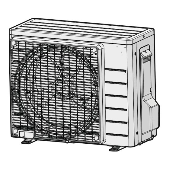
Daikin R32 Split Series Installationshandbuch
WARNING
• Do not use tapped wires, extension cords, or starburst connections, as they may cause overheating, electric shock, or fire.
• Do not use locally purchased electrical parts inside the product. (Do not branch the power for the drain pump, etc., from the
terminal block.) Doing so may cause electric shock or fire.
• Be sure to install an earth leakage circuit breaker. (One that can handle higher harmonics.)
(This unit uses an inverter. Therefore, an earth leakage circuit breaker capable of handling higher harmonics must be used in
order to prevent the earth leakage circuit breaker malfunctioning.)
• Use an all-pole disconnection type circuit breaker with at least 3mm (1/8 inch) between the contact point gaps.
• When carrying out wiring, take care not to pull at the conduit.
• Do not connect the power wire to the indoor unit. Doing so may cause electric shock or fire.
• Do not turn on the circuit breaker until all work is completed.
1) Strip the insulation from the wire (20mm).
2) Connect the inter-unit wires between the indoor and outdoor units so that the terminal numbers match. Tighten the terminal
screws securely. It is recommended that a flathead screwdriver be used to tighten the screws.
The screws are packed with the terminal block.

SPECIAL PRECAUTIONS WHEN DEALING WITH R32 UNIT

R32 charge, kg
Models
for 7.5m piping
FTXC20D - RXC20D
FTXC25D - RXC25D
FTXC35D - RXC35D
FTXC50D - RXC50D
FTXC60D - RXC60D
FTXC71D - RXC71D
Max. Allowable Length (L),m for:-
*
FTXC20/25/35D - RXC20/25/35D : 20
FTXC50/60/71D - RXC50/60/71D : 30
• Installation of pipe work shall be kept to a minimum and pipe work shall be protected from physical damage and shall not be
installed in an unventilated space.
• Reusable mechanical connectors and flare joints shall be accessible for maintenance purposes.
WIRING
Firmly fix the wires with
the terminal screws.
Inter-unit wire 4-core 60245
IEC 57 H07RN-F
1
Indoor
2
3
unit
Firmly fix the wires
with the terminal
screws.
Power supply
terminal block
1
2
3
Shape wires so
L
that the service
lid and stop valve
N
cover fit securely.
Minimum floor area, Xm
(based on 7.5m piping)
0.55
0.29
0.55
0.29
0.75
0.54
1.00
0.95
1.10
1.15
1.15
1.26
Power supply wire
3-core 60245 IEC 57
1 2 3
L N
H07RN-F
Power supply
Circuit
Earth leakage
breaker
circuit breaker
50Hz 220-240V
RXC20/25/35
*
Earth
RXC50/60/71
*
R32 charge, kg for max
2
allowable pipe length
*
0.76
0.76
0.96
1.38
1.48
1.53
16A
16A
Minimum floor area, Xm
on max allowable pipe length
0.55
0.55
0.88
1.82
2.10
2.24
ENGLISH
(based
2
)
*
12