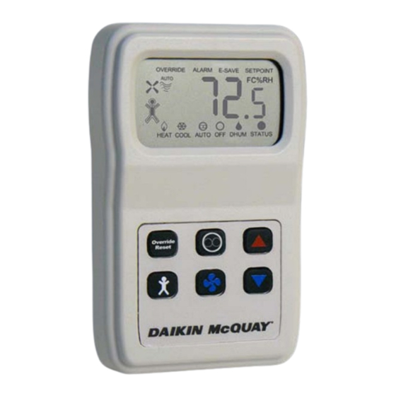
Daikin McQuay 910121754 Installation & Maintenance Data - Seite 8
Blättern Sie online oder laden Sie pdf Installation & Maintenance Data für Zubehör Daikin McQuay 910121754 herunter. Daikin McQuay 910121754 16 Seiten. Digitally adjustable display sensor for water source heat pumps smartsource gs series; smartsource gt series; with microtech iii controls enfinity cch series; enfinity ccw series; enfinity vfc series; enfinity vfw series; enfinity lvc series; enfinity lvw

Setpoint Analog Range Tolerance
Table 3: Setpoint analog range tolerance
Setpoint Analog Tolerance
55° to 95°F Scale
-5° to +5°F Scale
@ 55°F (min.)
@ -5°F (min.)
@65°F
@-2.5°F
@75°F
@0°F
@85°F
@+2.5°F
@95°F (max.)
@+5°F (max.)
Sensor Error
Sensor Error
Initial Start-Up Occupied Sequence:
On initial installation power-up, the sensor is in "Occupied"
mode with a solid occupied icon and DC voltage at terminal
"U". If the "STATUS/DOT" input on Terminal 1 from the
controller indicates occupied ("ON" continuous), then the
unit continues to stay "Occupied". If the "STATUS/DOT"
input on Terminal 1 from the controller indicates unoccupied
(5 seconds "ON" then 5.5 seconds "OFF"), then the occupied
icon will flash the desired occupancy state every 8 seconds,
indicating to the user a mismatch of the desired occupied
status and system occupied status at the controller
Power Fail Start-Up Occupied
Sequence:
On a power failure, the sensor retains its last known desired
occupancy status in non-volatile memory. On restoration of
power, the sensor restores its last known desired occupancy
state from memory. The occupied icon will reflect this with a
solid (occupied) or hollow (unoccupied) indication and ter-
minal "U" will have voltage applied (occupied) or grounded
(unoccupied). If the "STATUS/DOT" input on Terminal 1
from the controller matches this occupancy state then the oc-
cupied status icon will continue to be solid or hollow depend-
ing on the last known state. If the "STATUS/DOT" input on
Terminal 1 from the controller is different from the sensor
occupied state, then the occupied icon will flash the desired
occupancy state every 8 seconds indicating to the user a
mismatch of the desired occupied status and system occupied
status at the controller.
Display Descriptions
Numerical Display
The factory setting default numerical display
shows current temperature (°F or °C) and toggles to humidity
and setpoint display every 5 seconds.
Figure 7: Sensor numerical display
Page 8 of 16 / IM 1171-3
Terminal 3 Analog Output
0.0 to 0.10 vdc
1.3 to 1.42 vdc
2.12 to 2.2 vdc
2.58 to 2.63 vdc
3.0 to 4.0 vdc
Full Scale ≈ 5 vdc
(Figure
7)
Adjusting The Setpoint (Temperature or
Humidity)
Whichever is displayed at the time, temperature or humidity:
•
Push the
or
button, the displayed setpoint can
be adjusted up or down.
•
After an adjustment, the setpoint is displayed for 5 seconds.
During the setpoint display push
to switch between the temperature display or the humidity
display.
•
Push the
or
button, the displayed setpoint
can be adjusted up or down. (See
Operation" on page 10
The unit can also be programmed in the field to "Setpoint
Only" display or Setpoint Lockout. See the
cian Adjustments"
on page 11.
Occupied Icon Indicator:
The Occupied Icon on the left side of the display indicates
whether the room sensor is in the Occupied or Unoccupied
Mode,
(Figure
8).
Figure 8: Occupied & unoccupied icons
= "Occupied"
Solid is Occupied and Hollow is Unoccupied.
•
A blinking icon every 8 seconds indicates an override
request that has not been fulfilled.
The Word "Override" On The Display:
The word "Override" indicator in the top left corner illu-
minates when the sensor is signalled by the "Status" input
(Terminal 1).
This is initiated from the Override/Reset Button at first and
then confirmed from the "Status" input code which keeps the
"Override" indicator on.
Figure 9: Override word on the display
(System Mode Button)
"Front Panel Button
for details.)
"Optional Techni-
= "Unoccupied"
