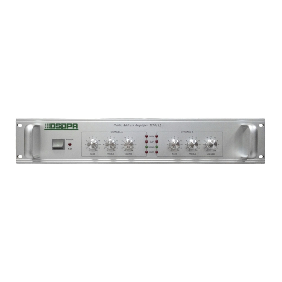
DSPPA MAG1312 Benutzerhandbuch - Seite 3
Blättern Sie online oder laden Sie pdf Benutzerhandbuch für Verstärken DSPPA MAG1312 herunter. DSPPA MAG1312 4 Seiten. Intelligent pa series

OPERATING PRECAUTIONS
l
Make sure the AC supply voltage is correct, it means the AC supply voltage must be as the
same as that printed on the rear panel of the amplifier. Damage caused by connecting the
amplifier to improper AC supply voltage is not covered by the three-year warranty.
l
Make sure the power switch is off before making any input or output connections.
l
To prevent speaker damage, it is always a good idea to turn the attenuator to minimum
before turn-on the amplifier if there is a high level signal at its input terminal.
l
The protection light on while operation means faults (e.g. overload or short-circuit)
happening. The power should be cut off immediately and should not be turn on before
correcting the faults.
l
Before turn on the device, using OUTPUT VOLTAGE SWITCH to set up the output voltage
value which matches the rated voltage of connecting speakers. The switch cannot be moved
during the operation.
Input Connections
Audio input connections are made via either the 3-pin
XLR-type connectors (Figure 1) or 6.3 mm sockets on
the rear panel.
EMC IN terminal only can receive the short-circuit signal which is compatible with DSPPA series
products.
Main Communication Interface can link with MAG peripheral control interface.
Communication Interface linking with Main Communication Interface of another amplifier to
make multiple device linkage.
Output Connections
l
Output terminals are on the rear panel. Speakers can be connected using banana plugs or
spade lugs. Speakers without volume controller should be connected with COM and HOT
terminals directly using broadcast line. Speakers with volume controller should be connected
with this amplifier's COM terminal and volume controller's SP terminal. Volume controller's
SP terminal R terminal and HOT terminal should be connected with the same terminals on
this amplifier. (Please refer to Rear Panel and Connections diagram)
Ground ( Ring)
Figure1 3-pin XLR-type
3
Signal (Hot)
1
2
3
connectors
