3onedata IES318-2F Handbuch zur Schnellinstallation
Blättern Sie online oder laden Sie pdf Handbuch zur Schnellinstallation für Netzwerk-Router 3onedata IES318-2F herunter. 3onedata IES318-2F 2 Seiten. Unmanaged industrial ethernet switch
IES318 series
Unmanaged Industrial Ethernet
Switch Quick Installation Guide
3onedata Co., Ltd.
Address: 3/B, Zone 1, Baiwangxin High Technology
Industrial Park, Xili, Nanshan District, Shenzhen
Website: www.3onedata.com
Tel:
+86 0755-26702688
Fax:
+86 0755-26703485
Package Checklist
Please check the integrity of package and accessories while
first using the switch.
1. Industrial Ethernet switch ⅹ1 (with wiring terminal block)
2. Manual
3. DIN-Rail mounting attachment
4. Certification
5. Warranty card
If any of these items are damaged or lost, please contact our
company or dealers, we will solve it asap.
Product Overview
The series products are unmanaged industrial Ethernet
switches, including the following models:
Model I IES318 (8 ports)
Model II IES318-1F (7 ports + 1 fiber port)
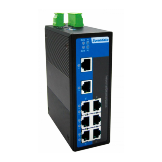
Model III IES318-2F (6 ports + 2 fiber ports)
Panel design
Rear view, Bottom view and Top view
Front view
Model I
Model II
1.
DIN-Rail mounting kit
2.
4-pin terminal block for power input
3.
Grounding screw
4.
Relay interface
5.
Console port
6.
DIP switch
7.
Running status indicator
8.
Alarm indicator
9.
Power supply indicator
10. 100Base-TX connection status indicator
11. 100Base-TX
12. 100Base-FX connection status indicator
13. 100Base-FX
Mounting Dimension
Unit (mm)
DIN-Rail Mounting
For convenient usage in industrial environments, the product
adopts 35mm DIN-Rail mounting, mounting steps as below:
Model III
Step 1
Check if the DIN-Rail mounting kit is installed firmly.
Step 2
Insert the bottom of DIN-Rail mounting kit (one side
with spring support) into DIN-Rail, and then insert
the top into DIN-Rail.
Tips:
Insert a little to the bottom, lift upward and then
insert to the top.
Step 3
Check and confirm the product is firmly installed on
DIN-Rail, then mounting ends.
Disassembling DIN-Rail
Step 1
Device power off.
Step 2
After lift the device upward slightly, first shift out the
top of DIN-Rail mounting kit, then shift out the
bottom of DIN-Rail, disassembling ends.