3onedata IES6116-2F-P Handbuch zur Schnellinstallation - Seite 2
Blättern Sie online oder laden Sie pdf Handbuch zur Schnellinstallation für Netzwerk-Router 3onedata IES6116-2F-P herunter. 3onedata IES6116-2F-P 4 Seiten. Managed industrial ethernet switch
Auch für 3onedata IES6116-2F-P: Benutzerhandbuch (5 seiten)
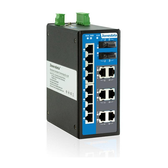
Front view
Model II
Model IV
Model VIII
Model X
1.
DIN-Rail mounting kit
2.
Grounding screw
3.
Relay alarm output terminal block
4.
Console port
5.
AC single power input terminal block
6.
DIP switch
7.
Device running indicator RUN
8.
Power supply input status indicator PWR
9.
Relay alarm indicator ALM
10.
10/100Base-T(X) Ethernet copper port
11.
Ethernet port connection indicator
12.
100Base-FX Ethernet fiber port
【Mounting Dimension】
Unit: mm
Attention before mounting:
Model VI
Don't place or install the device in area near water or
moist, keep the relative humidity of the device
surrounding between 5%~95% without condensation.
Before power on, first confirm the supported power
supply specification to avoid over-voltage damaging the
device.
The device surface temperature is high after running;
please don't directly contact to avoid scalding.
【DIN-Rail Mounting】
For convenient usage in industrial environments, the product
adopts 35mm DIN-Rail mounting, mounting steps as below:
Step 1
Check whether the DIN-Rail mounting kit that
comes with the device is installed firmly.
Step 2
Insert the bottom of DIN-Rail mounting kit (one side
with spring support) into DIN-Rail, and then insert
the top into DIN-Rail.
Tips:
Insert a little to the bottom, lift upward and then insert
to the top.
Step 3
Check and confirm the product is firmly installed on
DIN-Rail, and then mounting ends.
【Disassembling DIN-Rail】
Step 1
Power off the device.
Step 2
After lift the device upward slightly, first shift out the
top of DIN-Rail mounting kit, and then shift out the
bottom of DIN-Rail, disassembling ends.
Attention before powering on:
Power ON operation: first connect power line to the
connection terminal of device power supply, and then
power on.
Power OFF operation: first unpin the power plug, and
then remove the power line, please note the operation
order above.
【Power Supply Connection】
DC dual power supply
The products of model I, model III,
model V, model VII, model IX support
DC dual power supply and provide 4
pins power supply input terminal blocks
and two independent DC power supply
systems of PWR1 and PWR2.
Power supply range: 12~48VDC
AC single power supply
The products of model II, model IV,
model VI, model VIII, model X support
AC single power supply and provide 4