3onedata IES6116-4F-P Benutzerhandbuch - Seite 2
Blättern Sie online oder laden Sie pdf Benutzerhandbuch für Netzwerk-Router 3onedata IES6116-4F-P herunter. 3onedata IES6116-4F-P 5 Seiten. Managed industrial ethernet switch
Auch für 3onedata IES6116-4F-P: Handbuch zur Schnellinstallation (4 seiten)
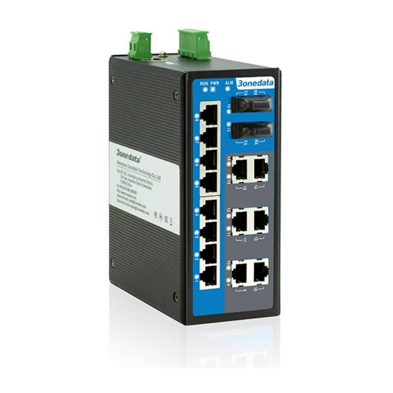
Front panel view
1. Ground screw
2. 2-pin terminal block for relay output
3. Console port
4. Power input terminal block
5. DIP switches for default factory
6. DIN-Rail mounting kit
7. System running LED
8. Power indicator
9. Relay alarm LED
10. Link/ACT LEDs
11. 10Base-T /100Base-TX Ethernet port
12. 100Base-FX fiber port
【Dimension】
The series of products are the same size, and the number of
the Ethernet interface is different. Unit (mm)
【Power supply input】
DC Series Switch:
The product top panel provided 4 bit power supply input
terminal block, support DC input. DC power supply input
supported redundancy function, provided PWR1 and PWR2
- 2 -
power input, can use for single, and can connect 2
separately power supply system, use 1 pair terminal block
connect the device at the same time. If one of the power
systems broke, the device can work un-interruptible. Built-in
overcorrect protection, Reverse connection protection.
Voltage input range is 12~48VDC (terminal block defined
as: V1-、V1+、V2-、V2+).
AC Series Switch:
The Industrial Ethernet switches have singe power and
redundancy power two kinds of power input. The singe
power AC series top panel provides 3 bit terminal block for
100~240VAC/DC power entered (L/+, PG, N/-)
Important notice:
1. Power ON operation: first of all, insert power cable's
terminal block into device's power port, then insert power
supply plug into power source
2. Power OFF operation: First off all, unpin power plug, then
strike the terminal block, please take care of operation
sequence.
【DIP Switch】
Top panel provided 4 bits DIP switch to do function configure
(ON to enable effective). 1 and 4 keep for future function. 2
is for upgrade. 3 is recovery default factory. Please power off
and power on when you change the status of DIP switch.
【Relay connection】
Relay access terminals in the top panel of the device.
Between the two terminal relay, as an open circuit state in
normal non alarm state, when there is any alarm information