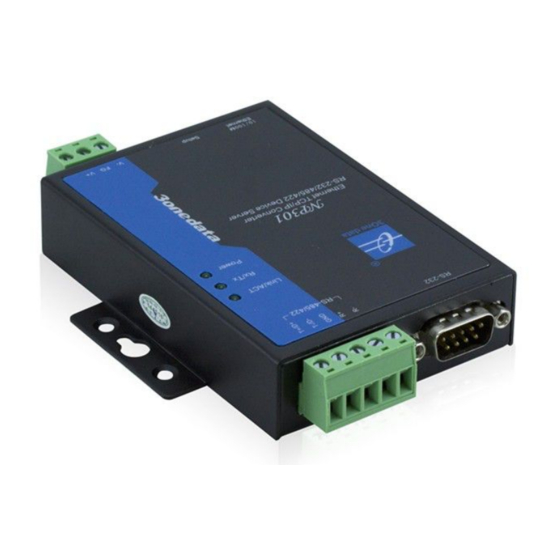
3onedata NP301 Handbuch zur Schnellinstallation - Seite 2
Blättern Sie online oder laden Sie pdf Handbuch zur Schnellinstallation für Server 3onedata NP301 herunter. 3onedata NP301 3 Seiten. Device server

downward, then tighten the screw to enhance
stability, mounting ends.
Device Disassembling
Step 1
Device power off.
Step 2
Unscrew the screw on the wall about 2mm.
Step 3
Lift the device outward slightly; take out the device,
disassembling ends.
【Power Supply Connection】
DC power supply
This device provides 3-pin power supply input
terminal blocks (V-, FG, V+). The power supply
support anti-reverse protection.
Power supply range: 9~48VDC
Note:
Power ON operation: first connect power line to the
connection terminal of device power supply, then power
on.
Power OFF operation: first unpin the power plug, then
remove the power line, please note the operation order
above.
【Restore Default Settings】
Setup is restoring default
settings button. Restoring
default settings steps as
follows: Press and hold the
setup button, disconnect the power supply and then give the
device to power up, wait for about 3~4 seconds to restore the
factory settings.
【Serial Port Connection】
This device provides 1-port RS-232 or RS-485/422 serial port
optional.
RS-232 serial port
RS-232 adopt DB9-Male connecter, the pin
definition is shown in the follow table:
PIN
1
2
3
4
5
–
RS-232
RXD TXD DTR GND DSR RTS CTS
RS-485/422 serial port
RS-485/422 adopt 5-pin 5.08mm pitch
industrial terminal blocks.
definition is shown in the follow table:
PIN
1
2
3
RS-485
D+
D-
GND
RS-422
T+
T-
GND
【Checking LED Indicator】
The device provides LED indicators to monitor the device
working status with a comprehensive simplified
troubleshooting; the function of each LED is described in the
table as below:
LED
Indicate Description
The power connection is operating
ON
normally.
PWR
The power is not connected or is not
OFF
working properly.
The Ethernet interface has established an
ON
active network connection.
The Ethernet interface is in a network
LINK
Flashing
activity state.
The Ethernet interface does not establish
OFF
an active network connection.
No data or abnormal data is being
Rx/Tx OFF
received or transmitted through serial port.
Flashing Serial port is receiving or transmitting data.
【Logging in to WEB Interface】
This device supports WEB management and configuration.
Computer can access the device via Ethernet interface. The
way of logging in to device's configuration interface via IE
browser is shown as below:
Step 1
Configure the IP addresses of computer and the
device to the same network segment, and the
6
7
8
9
network between them can be mutually accessed.
–
Step 2
Enter device's IP address in the address bar of the
computer browser.
The pin
Step 3
Enter device's username and password in the login
window as shown below.
4
5
–
–
R+
R-
Step 4
Click "OK" button to login to the WEB interface of
the device.
Note:
The default IP address of the device is "192.168.1.254".
The default username and password of the device is
"admin".
If the username or password is lost, user can restore it to
factory settings via device DIP switch or management
software; all modified configurations will be cleared
