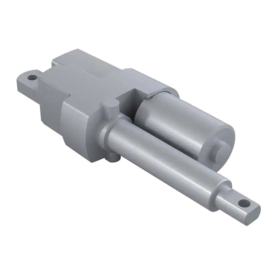
Duff-Norton 7415 Series Handbuch für Installation, Betrieb und Wartung - Seite 2
Blättern Sie online oder laden Sie pdf Handbuch für Installation, Betrieb und Wartung für Controller Duff-Norton 7415 Series herunter. Duff-Norton 7415 Series 16 Seiten. Electromechanical linear actuators

Section I
1-1.
General ............................................................................................................................................3
1-2.
Industrial Use Only .........................................................................................................................3
1-3.
Factory Preparation ........................................................................................................................3
1-4.
Warranty and Warranty Repair .......................................................................................................3
1-5.
Specifications .................................................................................................................................3
Table 1-1.
6415 Series DC Actuator Specifications .......................................................................................3
Table 1-2.
6415 Series DC Super Pac Actuator Duty Cycle ...........................................................................3
1-6.
Dimensions and Specifications .....................................................................................................4
Figure 1-1.
SPA-6415 and SPA-7415 Technical Illustration ............................................................................4
Figure 1-2.
Limit Switch Wire Color Diagram ..................................................................................................4
Section II
2-1.
Installation Procedures ..................................................................................................................5
2-2.
Limit Switch Adjustment ...............................................................................................................5
2-3.
Post-installation Procedures .........................................................................................................5
2-4.
Potentiometer Installation .............................................................................................................5
2-5.
Digital Position Indicator ...............................................................................................................6
Section III
3-1.
Operational Procedures .................................................................................................................6
Section IV
4-1.
Lubrication ............................................................................................................................. 7
4-2.
Required Tools ....................................................................................................................... 7
4-3.
General Procedures ................................................................................................................ 7
4-4.
Disassembly ........................................................................................................................... 7
4-5.
Assembly ............................................................................................................................... 8
Section V
Parts List for 6415 and 7416 AC Actuator .................................................................................12
Figure 5-1.
Exploded Parts Illustration 6415 & 7415 Series AC Actuator ...................................................13
Section VI
6-1.
Brake Alignment ...........................................................................................................................14
Figure 6-1a.
Brake Spring, Motor and Pinion Coupling Alignment .................................................................14
Figure 6-1b.
Brake Spring, Motor and Pinion Coupling Alignment .................................................................14
6-2.
Limit Switch Wiring Diagram .......................................................................................................14
Figure 6-2.
Limit Switch Wiring Diagram, 6415 and 7415 Series AC Actuator ...........................................14
6-3.
Limit Switch Assembly ................................................................................................................14
Contents
2
