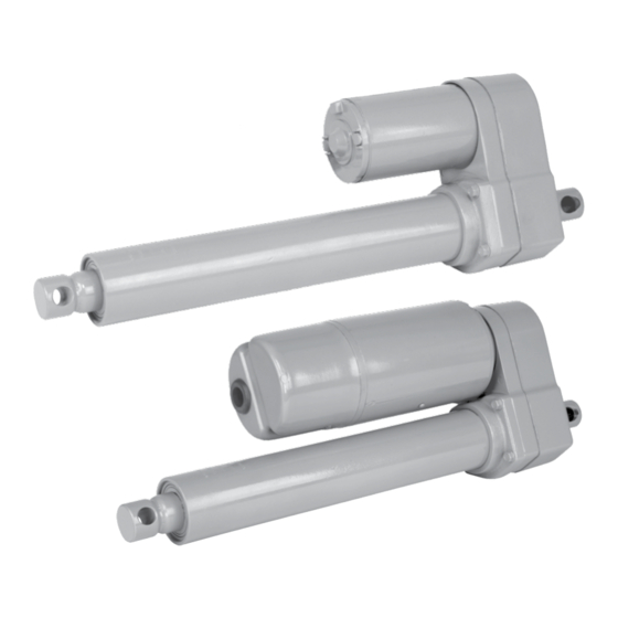
Duff-Norton TAP05-2A10 Series Installations-, Betriebs- und Wartungsanweisungen - Seite 2
Blättern Sie online oder laden Sie pdf Installations-, Betriebs- und Wartungsanweisungen für Controller Duff-Norton TAP05-2A10 Series herunter. Duff-Norton TAP05-2A10 Series 12 Seiten.

1-1.
General Information ...................................................................................................................3
1-2.
Application Information .............................................................................................................3
1-3.
Inspection ...................................................................................................................................3
Figure 3-1.
Dimensions in Inches .................................................................................................................3
1-4.
Warranty and Warranty Repair ...................................................................................................3
Table 1-1.
TA500 Performance at Rated Load ............................................................................................4
Table 1-2.
TA1000 Performance at Rated Load ..........................................................................................4
Section II
2-1.
Clevis Connections ....................................................................................................................4
2-2.
Motor Capacitor .........................................................................................................................4
2-3.
Wiring Connections ...................................................................................................................4
Figure 2-1.
Wiring Schematic .......................................................................................................................4
Figure 2-2.
Terminal Block Connections (AC) ............................................................................................5
Figure 2-3.
Wiring Schematic DC with Clutch ............................................................................................5
2-4.
Limit Switch Adjustment ...........................................................................................................5
2-5.
Potentiometer Adjustment ..........................................................................................................5
Section III
3-1.
Motor..........................................................................................................................................6
3-2.
Clevis Pins .................................................................................................................................6
3-3.
Jamming .....................................................................................................................................6
Section IV
4-1.
Lubrication .................................................................................................................................7
4-2.
Disassembly ...............................................................................................................................7
4-3.
Load Bearing ..............................................................................................................................7
4-4.
Reassembly ................................................................................................................................7
Section V
Parts Lists and Technical Illustrations
Table 5-1.
Linear Actuator Parts List ........................................................................................................8
Figure 5-1.
Linear Actuator Exploded Illustration .......................................................................................9
Table 5-2.
Limit Switch Parts List ............................................................................................................10
Figure 5-2.
Limit Switch Exploded Illustration ..........................................................................................11
Contents
2
