3onedata 277A Handbuch zur Schnellinstallation - Seite 2
Blättern Sie online oder laden Sie pdf Handbuch zur Schnellinstallation für Modem 3onedata 277A herunter. 3onedata 277A 3 Seiten. Serial port to fiber modem
Unit: mm
Model Ⅰ
Model Ⅱ, Model Ⅲ
External power supply:
Built-in power supply:
Note before mounting:
Don't place or install the device in area near water or
moist, keep the relative humidity of the device
surrounding between 5%~95% without condensation.
Before power on, first confirm the supported power
supply specification to avoid over-voltage damaging the
device.
The device surface temperature is high after running;
please don't directly contact to avoid scalding.
【Installation of Wall-mounted Device】
Step 1
Place the device on the wall for reference or
reference the mounting dimension to mark the
position of 2 screws.
Step 2
Place the device on marked wall and tighten the
screw to marked position, mounting ends.
【Disassembling of Wall-mounted Device】
Step 1
Power off the device.
Step 2
Hold the device and screw out the bolt on the wall.
Step 3
Take out the device, disassembling ends.
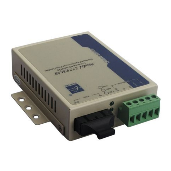
【Power Supply Connection】
5VDC power supply input
The external power supply of model Ⅱ and model Ⅲ
supports 5VDC power supply input. DC round-head,
inner ring is the positive pole, outer ring is the negative pole.
model Ⅲ supports 2.0A overcurrent protetion. Power supply:
5VDC.
12~48VDC power supply input
Model Ⅰ provides 2-pin terminal blocks and supports
12~48VDC power supply input. The pin definition as
follows:
Pin
1
Pin definition
GND
-48VDC power supply input
The built-in power supply of DC series
products model Ⅱ and model Ⅲ supports
-48 VDC power supply input, the pin
definition as follows:
Pin
1
2
Pin definition
GND
-48VDC+
220VAC power supply input
The built-in power supply of AC series
products model Ⅱ and model Ⅲ supports
220VAC power supply input. Power supply
input range: 100~240VAC/DC.
Note:
Power ON operation: first insert the power supply
terminal block into the device power supply interface,
and then plug the power supply plug contact.
Power OFF operation: first unpin the power plug, then
remove the terminal block wiring part; please note the
operation order above.
【Serial Port】
RS-232 serial port
Model Ⅱ provides 1 RS-232 serial port and
adopts DB9 female. The pin definition as
follows:
Pin
2
3
RS-232
OUT
IN
RS-485/422 serial port
Model Ⅲ provides 1 RS-485/422 serial port
and adopts 5-pin terminal blocks. The pin
definition as follows:
Pin
1
2
3
RS-485
GND
-
-
2
DC IN
3
-48VDC-
5
GND
4
5
D+
D-