Danfoss 40 Installationshandbuch - Seite 5
Blättern Sie online oder laden Sie pdf Installationshandbuch für Controller Danfoss 40 herunter. Danfoss 40 16 Seiten. Ultrasonic energy meter
Auch für Danfoss 40: Betriebshandbuch (16 seiten), Anleitung zur Kalibrierung (8 seiten)

Installation guide
1.3.
Mounting of flow sensor
Pipe position: No limitations but avoid positions
where air can be collected.
Inlet/outlet conditions (only for DN 65-DN 100)
In order to maximize performance it is necessary to have straight inlet and outlet flow conditions before
and after the flow sensor: 5 × DN on inlet and 3 × DN on outlet of flow sensor.
1.4.
Mounting and sealing of calculator
Heat meter calculator may be installed in heated premises, working ambient temperature shall
be not more than 55 °C. It may not be exposed to direct sunlight.
The calculator is mounted on an auxiliary holder (it can be oriented in the required direction at an angle of
each 90 °:
The possible ways of the mounting of the calculator (auxiliary holder):
- Direct mounting on the housing of the flow sensor, by turning each 90o (only when the flow temperature
does not exceed 90oC):
5 | © Danfoss | Energy Meters | 2021.10
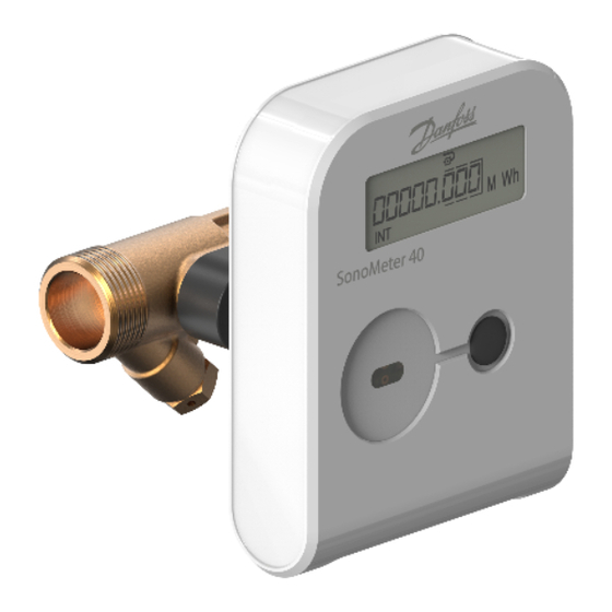
SonoMeter 40
5 x DN
flow
Rotation in pipe axis: Flow sensor should be angled
in 45 to 315° to avoid air collection in flow sensor.
3 x DN
AN384648824392en-010102
