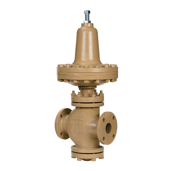
cashco 8310HP-1+6 Handbuch für Installation, Betrieb und Wartung
Blättern Sie online oder laden Sie pdf Handbuch für Installation, Betrieb und Wartung für Controller cashco 8310HP-1+6 herunter. cashco 8310HP-1+6 10 Seiten. Differential pressure reducing regulators

ISO Registered Company
MODELS 8310HP DIFFERENTIAL
(1+6 and 1+8 ) PRESSURE REDUCING REG U LA TORS
l.
DESCRIPTION AND SCOPE
The Models 8310HP-1+6 and 8310HP-1+8 are differential reducing regulators used to control dif fer en tial pressure between
downstream (outlet or P
(DN50), 2-1/2" (DN65), 3" (DN80) and 4" (DN100). Widely applied in steam atomization systems using heavy oil (Nos. 3-6,
Bunker C) to fuel burners. Refer to Tech ni cal Bulletin 8310HP-DIFF-TB for design conditions and selection recommendations.
II. INSTALLATION
1.
An inlet block valve should always be installed. An outlet
block valve is desirable.
2.
A manual bypass valve is recommended for "hot piping"
systems to assist in piping warm-up at startup.
3.
An isolation valve on the loading line is not recommended.
The threaded port in the diaphragm ring (25) for the
Model 8310HP 1+8 may be piped to a safe drainage
point, but no valve should be installed in the drain line.
4.
Pipe unions are recommended for NPT screwed
in stal la tions to allow removal from piping.
5.
An outlet pressure gauge should be located
ap prox i mate ly ten pipe diameters downstream, and
within sight. A loading pressure (or differential pressure)
gauge is rec om mend ed.
6.
All installations should include a downstream re lief
device if the inlet pressure could exceed the pres sure
rating of any downstream equipment or the max i mum
outlet pressure rating of the unit.
DO NOT HYDROSTATIC TEST THRU AN IN STALLED
UNIT; ISOLATE REGULATOR FROM TEST. DO NOT
HY DRO STAT IC TEST THE LOADING PRESSURE
WITH OUT PRESSURE IN THE MAIN REGULATOR.
The upper range spring pressure level listed on the name plate
is the rec om mend ed "up per operative limit" for the sens ing
di a phragm (see Section IV. Start-up, Number 7.) High er pres-
sures could cause internal damage. In ad di tion, note on the
name plate that the Inlet and Outlet pres sure and tem per a ture
ratings are at dif fer ent levels.
INSTALLATION, OPERATION & MAINTENANCE MANUAL
) pressure and a loading (P
2
CAUTION
SECTION l
) pressure to the spring chamber. Available in sizes 1-1/2" (DN40), 2"
Load
SECTION II
(Shaded portion for steam/condensate systems)
Recommended Piping Schematic For
7.
Clean the piping of all foreign material including chips,
welding scale, oil, grease and dirt before in stall ing the
regulator. Strainers are rec om mend ed.
8.
In placing thread sealant on pipe ends prior to
en gage ment, ensure that excess material is re moved
and not allowed to enter the regulator upon start-up.
9.
Flow Direction: Install so the flow direction match es
the arrow cast on the body. Install an external sensing
line (1/2" O.D. (DN15) tubing minimum) from the 3/8"
(DN10) NPT con nec tion in needle valve (39) to a point
down stream, pref er a bly at gauge location.
10. Install oil loading pressure sensing line to spring chamber
(13) connection.
11. For long operational life with minimum maintenance,
install a strainer in the upstream line. If regulator pipe
line is ex pand ing to a larger pipe line, always connect
sensing line to the larger pipe line.
12. For best performance, install in well drained hor i zon tal
pipe, properly trapped, if a steam service ap pli ca tion.
IOM-8310HP-DIFF
TR
TR
Pressure Reducing Station
06/16
