Danfoss FH-RT Installations- und Betriebsanleitung - Seite 2
Blättern Sie online oder laden Sie pdf Installations- und Betriebsanleitung für Thermostat Danfoss FH-RT herunter. Danfoss FH-RT 6 Seiten. Wireless room thermostat and wireless base unit

These installation and operating instructions describe system function and technical data.
The system is a complete floor heating control system for individual rooms in dwellings, offices, institutions, business premises, etc.
The system is based on data transfer via radio, and is therefore quick and easy to install.
The system was developed to meet requirements for comfort, heat economy, flexibility and user-friendly operation.
Power
1
2
3
4
5
6
7
8
Mode
OK
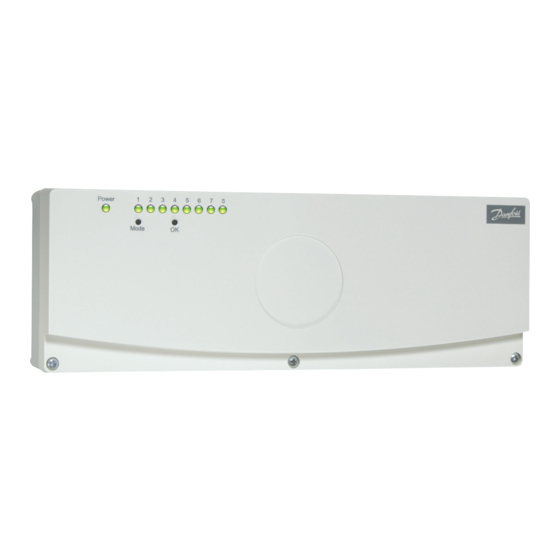
Fig. 1. The system consists of a base unit, thermostat and, if necessary, an external aerial.
2.0 Operating principle
The system consists of two unit types: base unit and thermostat.
The base unit is connected to a 230 V supply and through eight outputs
controls the thermal actuators that regulate the flow of hot water to the
individual rooms. The system can also control circulation pump and boiler.
The base unit is centrally located in the dwelling adjacent to the distribution
manifold.
2.1 Base unit
The base unit is the system interface. It consists of a control panel, radio
receiver and alarm.
If faults occur in the wireless data transfer, the base unit raises an alarm in
order to make users aware of the fault. The alarm also informs the user when a
thermostat requires a new battery. The receiver in the base unit continuously
scans the radio signals it receives from installed thermostats.
The base unit is usually installed about 1.5 metres above the floor in order
to make the control panel easily accessible. Installation at this height also
enhances the radio signal range of the system.
2.2 Thermostat
Up to eight thermostats can be connected to the system. One thermostat
can be used to control several thermal actuators. Thermostats are positioned
at suitable locations in rooms where temperature control is required.
Thermostats have a knob for setting the desired temperature and a switch
for selecting one of three programs (day, timer control and night).
Each thermostat contains a small battery that supplies current to an electronic
temperature measuring circuit with associated radio transmitter. At suitable
intervals the measured temperature is sent as a radio signal to the radio
receiver in the base unit. If the temperature is changed the thermostat will
transmit the new temperature after the suitable interval. For transmission
test please see section on Transmission Testing, or Thermostat Test Mode.
Thermostats have no external cable connections.
Each thermostat has a unique identification (ID) number that is sent with
every transmission. The base unit uses these ID numbers to distinguish
the various thermostats. Thermostats must therefore be registered in the
base unit before the unit is able to receive data from the thermostats.
During registration, thermostats transfer their ID numbers to the base unit.
The use of ID numbers also prevents the base unit from reacting to signals
received from neighbouring systems or other systems based on radio
technology.
2
10
Thermostats are battery powered and thus fully mobile, making it easy to
re-configure the system if required.
The system is CE marked and approved for use in all EU and former EFTA
countries.
The actual temperature is measured by the thermostat. When the actual
temperature is lower than the set temperature, a command for heat is sent
to the base unit.
Temperature can be set between 6°C and 30°C. A function switch on the
thermostat allows day, timer control or night to be selected. The day setting
allows normal operation, the timer setting allows time-controlled night set-
back to be used, and the night setting permanently lowers the temperature
setting by 4°C.
Thermostats are supplied with pre-installed batteries. Before being taken
into use, thermostats are "dormant" and only begin measuring temperature
and transmitting data on being registered in the base unit for the first time.
The purpose of this dormant state is to minimise energy use during storage
and to avoid unnecessary radio transmission.
On being installed for the first time, thermostats automatically enter test
mode so that transmission can be tested immediately.
Battery life is guaranteed by the manufacturer to be at least 5 years.
A complete system is illustrated above in Fig. 1.
2.3 Aerial
Normally, the base unit uses a built-in aerial.
The location of the base unit is therefore important for the range, which can
be increased by equipping the base unit with an external aerial.
An external aerial must be used if the base unit is located in a metal
cabinet.
20
30
