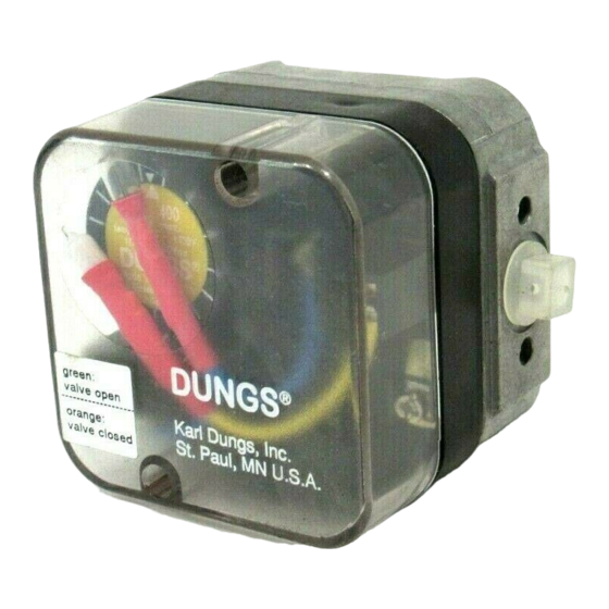
Dungs CPI 400 Installationshandbuch
Blättern Sie online oder laden Sie pdf Installationshandbuch für Schalter Dungs CPI 400 herunter. Dungs CPI 400 2 Seiten. Valve switch and position indicator

CPI 400 Valve Switch and Position Indicator
Installation Manual
Closed position indicator CPI 400 visually and electrically indicates when the valve is either in the closed or open position.
Mounts directly to the DMV, SV, and MVD series valves. When the valve is closed a orange light is visible, when the valve
is open a green light is visible.
Gases
Natural gas, propane, butane, noncorrosive gases,
and air. Suitable for up to 0.1% by volume, dry H
used with nickel plated brass adatper.
Switch Type
SPDT
Switch Action
Valve open:
Green light
Valve closed: Orange light
Contact Rating
10 A res, 8 FLA, 48 LRA @120 Vac. 1A max @ 24Vdc and
1A max @ 12Vdc. When used, the 24Vdc/Vac indicator
light consumes 20mA when enegized.
Enclosure
NEMA Type 4
• Read these instructions carefully.
• Failure to follow them and/or improper installation may
cause explosion, property damage and injuries.
• Installation must be done with the supervision of a
licensed burner technician.
• Check the ratings in the specifications to make sure that
they are suitable for your application.
• Never perform work if gas pressure or power is applied,
or in the presence of an open flame.
Mounting
• The valve must be de-energized and the gas supply shut
off before mounting the CPI.
• Disconnect all power to the switch before beginning to
prevent electrical shock and equipment damage.
Mounting Procedure (reference Fig. 1 above)
• IMPORTANT!! Before mounting the brass adapter
to the valve or to the CPI 400, use your fingers to
verify that the pin slides freely inside the brass
adapter. If this pin does not slide freely, apply a
large enough force to the appropriate side to free
the pin.
• Using a 5mm hex wrench, remove the plug and its o-ring
located at the bottom of the valve.
• Verify that the brass adapter has a clean o-ring and its
threads and the groove into which the brass adapter
mounts, are clean and in good condition.
1 ... 2
524 Apollo Drive, Suite 10 Lino Lakes, MN 55014 U.S.A.
2011 Williamsburg Road Richmond, VA 23231 USA
Phone: (651) 792-8912 Fax: (651) 792-8919 E-mail: [email protected]
Phone: 804.236.3800 Fax: 804.236.3882 E-Mail: [email protected]
SPECIFICATIONS
S when
2
ATTENTION
• Once installed, perform a complete checkout including
leak testing.
• Verify proper operation after servicing.
• The system must be installed, used, and maintaned to
meet all applicable national and local code requirements
such as but not limited to NFPA 86, CSD-1, ANSI Z21.13,
UL 795, NFPA 85, or CSA B149.3.
MOUNTING
• Mount the brass adapter into the valve.
• Use a 9/16" (14 mm) open end wrench and torque to 44
in-lbs (5Nm), which is about 1/4 turn (after finger tight).
DO NOT overtighten.
• Mount the CPI switch onto the brass adapter. Push the
CPI housing towards the valve until it stops.
• Turn/Position the CPI so that the wiring and conduit con-
nection apply the least amount of torque as possible.
• Tighten the set screw so that the CPI housing is secured
to the brass adapter.
• Do not turn the CPI 400 after tightening the set screw;
this may strip the brass adapter. The brass adapter could
loosen and the assembly may leak.
• Perform a leak test to verify that no leakage occurs around
the o-ring.
Karl Dungs, Inc
Power Equipment Company
Fig. 1
