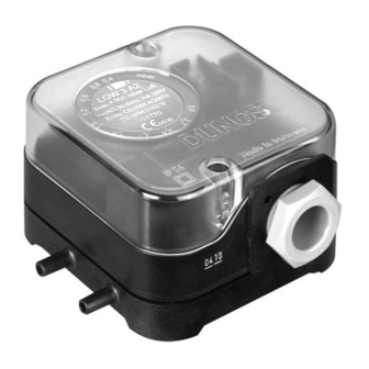
Dungs LGW A2 Series Bedienung und Montageanleitung - Seite 3
Blättern Sie online oder laden Sie pdf Bedienung und Montageanleitung für Schalter Dungs LGW A2 Series herunter. Dungs LGW A2 Series 8 Seiten. Air pressure switch, air pressure switch with test button
Auch für Dungs LGW A2 Series: Bedienung und Montageanleitung (8 seiten), Anleitung Handbuch (12 seiten), Bedienung und Montageanleitung (6 seiten)

Gerät darf nicht als Hebel
–
benutzt werden.
Made in Germany
Do not use unit as lever.
Ne pas utiliser le pressostat
comme un levier.
L'apparecchio non deve es-
sere usato come leva.
Druckanschluß LGW...A2
Geeignete Schläuche (für Luft,
Rauch- und Abgase) einsetzen.
Schlauchinnendurchmesser A
max. 4 mm
Schlauchaußendurchmesser B
max. 15 mm
Schläuche gegen unbeabsichtigtes
–
Abziehen sichern: Kabelbinder
oder Schlauchschelle oder Ω
Made in Germany
- Schelle.
A
B
Einbau
LGW...A2P
1. Der Druckwächter wird direkt
auf einen Rohrstutzen mit R 1/4
Außengewinde aufgeschraubt.
Bild 1.
2. Nach Einbau Dichtheits- und
Funktionskontrolle durchführen.
Auf vibrationsfreien Ein-
bau achten! Bild 2.
1
Nr. No. 14
Geeignetes
Dichtmittel
einsetzen!
Use proper seal-
ing compounds!
Utiliser une pâte
à joint adaptée!
Impiegare ma-
teriale di tenuta
adeguato!
3 ... 8
M
max.
–
2
T
max.
M
max.
LGW...A2 pressure connection
Use suitable hoses (for air, flue and
exhaust gases)
Max. 4 mm inner hose
diameter A
1
Max. 15 mm outer hose
diameter B
Secure hoses to prevent uninten-
–
2
tional removal: use cable tie or
cable clip or Ω clip.
–
Installation of
LGW...A2P
1. Screw the pressure switch directly
on a tube socket with R 1/4 outer
thread
–
(see Fig. 1).
2. After installation, perform a leak-
age and function test.
Ensure that the pressure
switch is installed free of
vibration! (see Fig. 2).
A
B
Nr. No. 22
DN
Rp
1/8
3
M
max.
T
max.
Prise de pression LGW...A2
Utiliser les tubes appropriés (pour
l'air, la fumée et les gaz brûlés).
Diamètre intérieur du tube A
max. 4 mm
Diamètre extérieur du tube B
max. 15 mm
Faire le nécessaire afin que les tubes
ne puissent pas être enlevés par
inadvertance: fixation par attache
Made in Germany
- collier ou clips Ω.
Made in Germany
Montage
LGW...A2P
1. Le pressostat peut se visser di-
rectement sur un piquage R 1/4"
Fig.1.
2. Après le montage contrôler la
Made in Germany
jonction et l'étanchéité.
Veiller à ce que l'appareil
ne subisse pas de vibra-
tions! Fig. 2.
2
6
8
1
1/4
–
2
–
2
1
35
[Nm] t ≤ 10 s
25
Made in Germany
20
[Nm] t ≤ 10 s
15
Attacco di pressione LGW...A2
Per aria, gas di combustione e di scarico,
impiegare tubi flessibili adeguati
Diametro interno del tubo A
max. 4 mm
Diametro esterno del tubo B
max. 15 mm
–
Assicurare i tubi contro il pericolo
–
2
Made in Germany
di distacco involontario servendosi
di serratubi, fascette per tubi o
Made in Germany
fascette a forma di Ω.
–
Made in Germany
Installazione
LGW...A2P
A
1. Il pressostato viene avvitato diret-
tamente su un tubo di sostegno
B
con filetto esterno R 1/4 (Fig.1)
2. Dopo il montaggio effettuare i
controlli di tenuta e funzionalità.
Evitare possibilità di vi-
brazioni! Fig 2.
