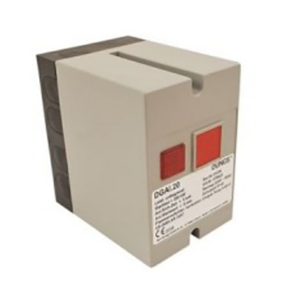
Dungs DGAI. 20/10 Betriebs- und Montageanleitung - Seite 4
Blättern Sie online oder laden Sie pdf Betriebs- und Montageanleitung für Kontrolleinheit Dungs DGAI. 20/10 herunter. Dungs DGAI. 20/10 6 Seiten. Automatic burner control for gas burners without blower with ignition gas valve

Flammenüberwachung
Eine lonisationselektrode dient als
Sonde in der Flamme, der Brenner
als Masse. Es ist darauf zu achten,
daß am Brenner eine gute Flam-
menhaftung gewährleistet ist. Der
Brenner muß mit dem "Gegenpol zur
Rückleitung des Ionisationsstromes"
gute Verbindung haben. Bei nor-
malen Netzverhältnissen liegt der
Gegenpol - N - auf Erdpotential. Es
genügt der Erd- bzw. Schutzleiteran-
schluß an Brennermasse.
Bei Versorgungsnetzen, bei denen
der Pol, welcher anstelle des N
angeschlossen wird, nicht geerdet
ist, z. B. bei Netzen ohne Erd- bzw.
Schutzleiter oder wenn die Versor-
gungsspannung zwischen 2 Phasen
abgegriffen wird, muß unbedingt ein
Isolier-Transformator benutzt und
dieser Pol geerdet werden.
Der Zündfunke kann evtl. den lo-
nisationsstrom abschwächen. In
diesem Falle wird empfohlen, die
Primäranschlüsse des Zündtrafos
zu vertauschen.
Überwachungsstrom-Messung mit
Gleichstrom-Mikroampèremeter.
Stromstärke im Betrieb: > 6 µA
Max. lonisationsstrom: ca. 50 µA
Störabschaltung bei lonisations-
strom < 1 µA.
Meßgeräteanschluß
Meter port
Branchement de l´appareil de
mesure
Collegamento dell'apparecchio
misuratore.
1
DGAI.
+
20
= 0...100 A
-
Flame detector
An ionization electrode acts as a
probe in the flame, the burner as
ground.
Make sure that proper flame adhe-
sion is ensured on the burner. The
burner must have good connection
to the counterpole to the return line
of the ionization current.
In normal network conditions, the
counterpole (N) is tied to ground.
Ground or protection line port to
burner ground is sufficient.
An isolating transformer must abso-
lutely be used in supply networks in
which the pole, which is connected
instead of the N contactor, is not
grounded (e. g. in networks without
a ground or protective conductor or
when the supply voltage is tapped
between two phases) and this pole
must be grounded.
The ignition spark may weaken the
ionization flow. In this case, we advice
you to exchange the primary termi-
nals of the ignition transformer.
Monitor current measurement using
dc micro-ammeter.
Current intensity in operation: > 6 µA
Max. ionization current: approx. 50 µA
Fault switch-off for ionization current
< 1 µA.
Abmessungen in mm
75
ø 4,5
PG 9
Surveillance de flamme
Une électrode d´ionisation sert de son-
de dans la flamme, le brûleur servant de
masse. Il faut veiller à assurer une bonne
adhérence de la flamme au brûleur. Le
brûleur doit être correctement relié au
pôle opposé pour le retour du courant
d´ionisation. Dans des conditions nor-
males du secteur électrique, le pôle
opposé - N - est sur le potentiel de
terre. Il suffit de brancher la terre ou le
conducteur de protection à la masse
du brûleur.
Pour les réseaux d´alimentation dans
lesquels le pôle qui est connecté à
la place du N n´est pas mis à terre,
par exemple, dans les réseaux sans
con-ducteur de mise à terre ou,
respec-tivement, sans conducteur
de pro-tection, ou si l´on préleve la
tension d´alimentation entre 2 phases,
il faut impérativement utiliser une trans-
formateur d´isolement ou mettre ce
pôle à la terre.
L'étincelle d'allumage peut éventu-
ellement affaiblir le courant d'ioni-
sation. Dans ce cas, il est conseillé
de permuter les branchements
primaires du transformateur d'allu-
mage.
Mesure du courant de surveillance
avec un micro-ampèremètre à cou-
rant continu.
Intensité en marche : > 6 µA
Courant d´ionisation maxi : 50 µA environ.
Coupure de panne pour courant
d'ionisation < 1 µA
Dimensions in mm
Dimensions en mm
110
70
ø 4,5
1
2
3 4 5 6 7 8 9
10
11
N
xx
25
ø 15,8
75
Sorveglianza della fiamma
L'elettrodo di ionizzazione serve come
sonda nella fiamma, il brucia-tore come
massa. Si dovrà fare attenzione, che
sul bruciatore sia garantita una buona
aderenza della fiamma. Il bruciatore
deve avere un buon collegamento con
il "polo opposto alla linea di ritorno del
flusso di ionizzazione". A condizioni di
rete normali il polo opposto N si trova
sul potenziale di terra. E'sufficiente un
collegamento a terra e rispettivamente
al con-duttore di protezione con la
massa del bruciatore.
Per reti d´alimentazione nelle quali il
polo che viene collegato al posto di
N, non è messo a terra (per es. per
reti senza conduttore di terra o di
protezione), oppure se la tensione
di alimentazione vienne presa tra
due fasi, si deve impiegare indis-
pensabilmente un trasformatore
isolante e questo polo deve essere
messo a terra.
La scintilla di accensione può
eventualmente indebolire la corrente
di ionizzazione. In qusto caso viene
consigliato di sostituire gli attacchi
primari del trasformatore di ac-
censione.
La misurazione della corrente di
sorveglianza avviene con micro-
amperometro a corrente continua.
Amperaggio in esercizio: > 6 µA.
Max. corrente di ionizzazione: ca. 50 µA.
Stacco per guasto a corrente di
ionizzazione die < 1 µA.
Dimensioni in mm
gn/ge
br
230 V
1x 5000 V
bl
Z
bl
blau
bl
br
braun
br
gn/ge grün/gelb
gr/ge vert/jaune
bl
blue
bl
br
brown
br
gn/ge green/yellow
gn/ge verde/giallo
PE
bleu
brun
blu
marrone
4 ... 6
