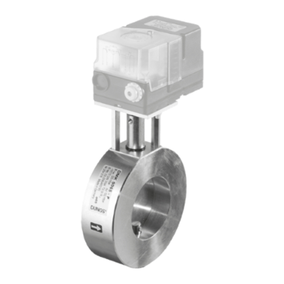
Dungs DMK 5125 Bedienung und Montageanleitung - Seite 4
Blättern Sie online oder laden Sie pdf Bedienung und Montageanleitung für Kontrolleinheit Dungs DMK 5125 herunter. Dungs DMK 5125 8 Seiten. Motor valve typ dmk

Durchflußdiagramm 1
DMK 5040 - DMK 5125
V
Klappenstellung 0°
min.
Klappe geschlossen
Durchflußdiagramm 2
DMK 5040 - DMK 5080
Klappenstellung V
90°
max.
Klappe offen
100
80
60
50
40
30
20
10
8
6
5
4
3
2
1
10
10
Flow diagram 1
DMK 5040 - DMK 5125
V
valve position 0°
min.
Valve closed
100
80
60
50
40
30
20
10
8
6
5
4
3
2
1
0,6 0,8
1,0
2
0,4
Vn [m
/h] Luft / Air / Aria dv = 1,00
3
0,6 0,8
1,0
2
Vn [m
/h] Erdgas / Natural gas / Gaz naturel / Gas metano dv = 0,65
3
Flow diagram 2
DMK 5040 - DMK 5080
Valve position V
90°
max.
Valve open
Arbeitsbereich
Working range
Zone de travail
Campo di lavoro
20
30
40 50 60
8090
100
Vn [m
/h] Luft / Air / Aria dv = 1,00
3
20
30
40 50 60
8090
100
Vn [m
/h] Erdgas / Natural gas / Gaz naturel / Gas metano dv = 0,65
3
Diagramme de débit 1
DMK 5040 - DMK 5125
V
position du papillon 0°
min.
papillon fermé
Basis
+ 15 °C, 1013 mbar, trocken
Based on
+ 15 °C, 1013 mbar, dry
Base
+ 15 °C, 1013 mbar, sec
Base
+ 15 °C, 1013 mbar, secco
3
4
6
10
5
7
8
9
20
3
4
5
6
7
8
9
10
20
30 40 50
Diagramme de débit 2
DMK 5040 - DMK 5080
V
position du papillon 90°
max.
papillon ouvert
200
300
400
600
800
1000
200
400
600
800
Diagramma portata 1
DMK 5040 - DMK 5125
V
posizione farfalla 0°,
min.
con farfalla chiusa
30 40 50
70 90
70 90
Diagramma portata 2
DMK 5040 - DMK 5080
Posizione farfalla V
farfalla aperta
Basis
+ 15 °C, 1013 mbar, trocken
Based on
+ 15 °C, 1013 mbar, dry
Base
+ 15 °C, 1013 mbar, sec
Base
+ 15 °C, 1013 mbar, secco
2000
4000 6000 800010000
4000 6000 800010000
20000
90°,
max.
20000
4 ... 8
