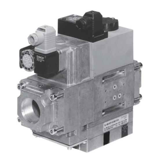
Dungs GasMultiBloc MB-VEF 425 B01 Anleitung Handbuch - Seite 10
Blättern Sie online oder laden Sie pdf Anleitung Handbuch für Kontrolleinheit Dungs GasMultiBloc MB-VEF 425 B01 herunter. Dungs GasMultiBloc MB-VEF 425 B01 20 Seiten. Gas-air-ratio control

Montagevorschrift
Impulsleitungen
Impulsleitungen p
, p
und
L
F
p
müssen ≥ DN 4 (ø 4 mm),
BR
PN 1 entsprechen und aus Stahl
gefertigt sein.
Andere Werkstoffe der Impulslei-
tungen nur nach Baumusterprü-
fung zusammen mit dem Brenner
zulässig.
Impulsleitungen müssen so
verlegt werden, daß kein
Kondensat in den MB-VEF zurück-
fließen kann.
Impulsleitungen müssen
sicher gegen Abriß und Ver-
formung verlegt sein.
Impulsleitungen kurz halten!
Leitungen/Impulsleitungen
nach Anschluß auf atmosphä-
rische Dichtheit prüfen, Lecksuch-
spray nur gezielt einsetzen.
Prüfdruck: p
= 100 mbar
max.
MB-VEF 415/420
Einbau Impulsleitungen
Installation of pulse lines
Montage des conduites d'impulsions
Installazione delle linee ad impulsi
1
p
: Gaseingangsdruck
e
S10/12:
5 - 100 mbar
S30/32:100 - 360 mbar
6
p
: Gebläsedruck, Luft
L
0,4 - 100 mbar
7
p
: Feuerraumdruck
F
– 20 mbar ... + 50 mbar
oder Atmosphäre
∆p
max. = p
- p
= 100 mbar
L
L
F
∆p
max. = p
- p
= 100 mbar
BR
L
F
8
p
: Brennerdruck, Gas
Br
0,5 - 100 mbar
Pulse line
assembly instructions
Pulse lines p
, p
and p
L
F
must correspond to ≥ DN 4
(4 mm dia.), PN 1 and they must
be made of steel.
Other materials for pulse lines
are only permitted after a type
test together with the burner.
Route pulse lines so that no
condensate can flow back
to the MB-VEF.
Secure pulse lines to prevent
them from being ripped out
and deformed.
Keep pulse lines short!
Test lines/impulse lines for
leakage to air. Use leakage
spray only if necessary.
Test pressure: p
= 100 mbar
max.
1
p
: Gas inlet pressure
e
S10/12:
5 - 100 mbar
S30/32:100 - 360 mbar
6
p
: Blower pressure, air
L
0,4 - 100 mbar
7
p
: Combustion chamber
F
pressure or atmosphere
– 20 mbar ... + 50 mbar
∆p
max. = p
- p
= 100 mbar
L
L
F
∆p
max. = p
- p
= 100 mbar
BR
L
F
8
p
: Burner pressure, gas
Br
0,5 - 100 mbar
Instructions de montage des
conduites d'impulsions
Les conduites d'impulsions
BR
p
, p
et p
doivent être en
L
F
BR
acier et avoir au moins PN1 et DN4.
Des conduites d'impulsions autres
qu' en acier ne pourront être utilisées
qu' après des essais et une homolo-
gation avec le brûleur.
Le montage des conduites d'impul-
sions doit être réalisé afin
d'éviter que des condensats
s'introduisent dans le MB-VEF.
Les conduites d'impulsions doivent être
protégées contre l'arrachement
et la déformation.
Les conduites d'impulsions
doivent être les plus courtes
possible!
Un contrôle d'étanchéité des conduites
sera réalisé après le montage.
Attention dans l'utilisation d'un
spray de détection de fuite.
Pression de contrôle:
p
= 100 mbar
max.
1
p
: Pression d'entrée du gaz
e
S10/12:
5 - 100 mbar
S30/32:100 - 360 mbar
6
p
: Pression de l'air
L
0,4 - 100 mbar
7
p
: Pression du foyer
F
– 20 mbar ... + 50 mbar
ou pression atmosphérique
∆p
max. = p
- p
= 100 mbar
L
L
F
∆p
max. = p
- p
= 100 mbar
BR
L
F
8
p
: Pression du brûleur, gaz
Br
0,5 - 100 mbar
Prescrizioni per il montaggio
delle linee ad impulsi
Le linee ad impulsi p
, p
e p
L
F
devono essere ≥ a DN 4 (ø
4 mm), e corrispondere a PN 1 ed
essere prodotte in acciaio.
Altri materiali delle linee ad impulsi
sono consentiti soltanto dopo che
si sarà potuto collaudarne un cam-
pione insieme al bruciatore.
Le linee ad impulsi dovranno
essere strutturate in modo
tale che non sia possibile l'infiltra-
zione di condensa nell'apparecchio
MB-VEF.
Le linee ad impulsi dovranno
essere a prova di rottura e di
deformazione.
Mantenere per le linee ad impulsi
un percorso breve
Dopo l'allacciamento con-
trollare la tenuta atmosferica
delle condutture e delle linee ad
impulsi. Usare gli spray cercafughe
soltanto in modo orientato.
Pressione di prova:
p
= 100 mbar
max.
1
p
: pressione gas in entrata
e
S10/12:
5 - 100 mbar
S30/32:100 - 360 mbar
6
p
: pressione al soffiante, aria
L
0,4 - 100 mbar
7
p
: pressione al vano caldaia
F
– 20 mbar ... + 50 mbar
o atmosfera
∆p
max. = p
- p
= 100 mbar
L
L
F
∆p
max. = p
- p
= 100 mbar
BR
L
F
8
p
: pressione al bruciatore,
Br
gas 0,5 - 100 mbar
BR
10 ... 20
