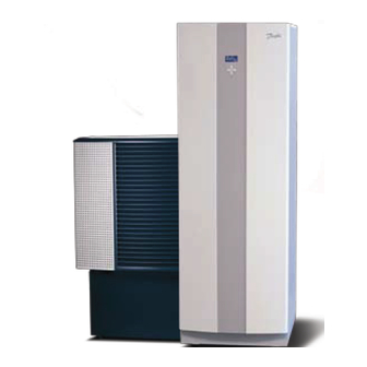
Danfoss DHP-A Installationsanleitung Handbuch - Seite 11
Blättern Sie online oder laden Sie pdf Installationsanleitung Handbuch für Kontrolleinheit Danfoss DHP-A herunter. Danfoss DHP-A 15 Seiten. Outdoor unit
Auch für Danfoss DHP-A: Installationsanweisung (6 seiten)

3.2.3
Unvented package installation, DHP-L Opti Pro models, DWH 200, DWH 300
10
11
91
96
DHP-L Opti Pro
Figure 5.
The principal installation solution of the unvented package on DHP-L Opti Pro models with DWH
Position
Name
10
Supply line heating system
11
Return line heating system
12
Cold water
13
Hot water
80
Shut-off valve
86
Safety relief valve heating system
91
Strainer
96
Flexible hose
104
Safety relief valve 2,5 bar
110
Expansion vessel
113
Expansion heating system
126
Factory fitted combined Temperature and pressure relief valve*
128
Double check valve with Shut-off valve
129
Unvented manifold assembly: Pressure reducing valve, Safety relief valve, Non-return valve
132
Flexible hose Unvented package
*
) The water heater tank in DWH is factory fitted with a Temperature and pressure relief valve . The connec-
tion from this valve must not be used for other purposes other than discharge pipe connection . Please see
chapter 5 .3 Discharge pipe arrangement .
DD E D
N ote! No valve should be fitted between the safety relief valve and the storage cylinder .
104
86
113
DWH 200
DWH 300
13
12
80
129
132
126
110
80
96
128
80
12
Unvented manifold assembly
(see figure 1)
Appendix UK – 11
