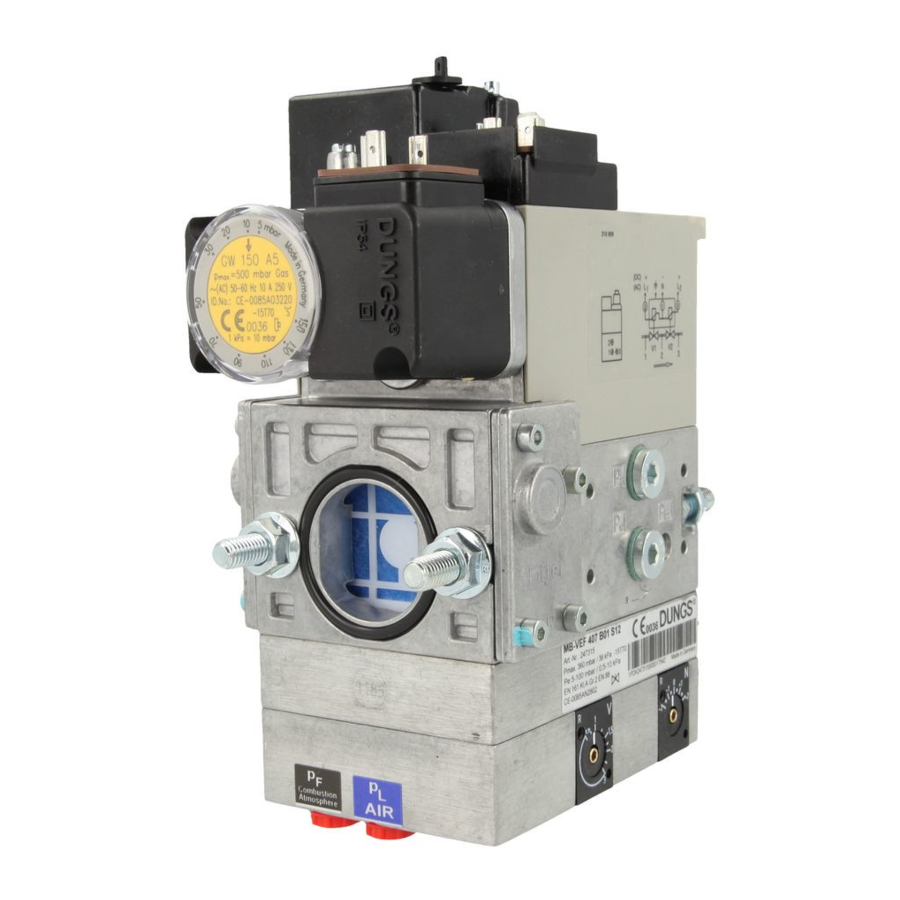
Dungs GasMultiBloc MB-VEF 412 B01 Bedienung und Montageanleitung - Seite 2
Blättern Sie online oder laden Sie pdf Bedienung und Montageanleitung für Controller Dungs GasMultiBloc MB-VEF 412 B01 herunter. Dungs GasMultiBloc MB-VEF 412 B01 16 Seiten. Gas-air-ratio control

Druckabgriffe
Pressure taps
Prises de pression
Manopola a pressione
1
0
7
1,3,4,6 Verschlußschraube G 1/8
2
Meßstutzen
5
Verschlußschraube M4
7,8,9
Innengewinde G 1/8 für
Impulsleitungen p
, p
,p
L
F
Br
Filterdeckel
0
Einbaumaße / Dimensions / Cotes d'encombrement / Dimensioni [mm]
g = Platzbedarf für Deckel des Druckwächters
g = space requirement for pressure switch cover
g = encombrement pour couvercle du pressostat
g = ingombro per il coperchio del pressostato
e = Platzbedarf für Magnetwechsel
e = space requirements for fitting solenoid
e = Encombrement pour changement de l'électroaimant
e = Ingombro per sostituzione bobina
Einbaumaße
Typ
Dimensions
Type
Cotes d'encombrement
Type
Dimensioni
Tipo
[mm]
a
b
MB-VEF 407 B01
110
151
120
MB-VEF 412 B01
140
185
145
Typ
Öffnungszeit
Rp
Type
Opening time
Type
Durée d'ouverture
Tipo
Tempo aperutra
MB-VEF 407 B01
Rp 3/4*
MB-VEF 412 B01
Rp 1 1/4*
max. Drehmomente / Systemzubehör
[Nm]
max. torque / System accesories
max. couple / Accessoires du système
max. coppie / Accessorio di sistema
Geeignetes Werkzeug einsetzen!
Please use proper tools!
Utiliser des outils adaptés!
Impiegare gli attrezzi adeguati!
Gerät darf nicht als Hebel be-
nutzt werden
Do not use unit as lever.
Ne pas utiliser la vanne comme
un levier.
L'apparecchio non deve essere
usato come leva.
2
6
9
V
N
N
8
4
3
5
1,3,4,6 G 1/8 screwed sealing plug
2
Measuring nozzle
5
M4 screwed sealing plug
7,8,9
G 1/8 female thread for
.
p
,p
,p
pulse lines
L
F
Br
Filter cup
0
c
d
e
f
g
160
185
70
40
175
245
80
40
P
I
max.
max.
[VA]
[A]
~(AC)
220 V .. 230 V
28
0,13
< 1 s
50
0,22
< 1 s
M
V
N
T
max.
2
0
1
1
0
V
7
0
5 3 4
1,3,4,6 Bouchon G 1/8
2
Prise de pression
5
Bouchon M4
7,8,9
Taraudage G 1/8 pour le
raccordement des pres-
sions p
, p
L
0
Couvercle du filtre
c
g
Einstellzeit
Setting time
Temps de réglage
Tempo di regolazione
EN 12067-1
< 1 s
< 1 s
M 4
M 5
M 6
M 8
2,5 Nm
5 Nm
7 Nm
15 Nm
Schrauben kreuzweise anziehen!
Tighten screws crosswise!
Serrer les vis en croisant!
Stringere le viti incrociate!
DN
10
Rp
3/8
max.
M
70
max.
M
max.
T
35
max.
3
4
p
p
2
e
a
2
3
4
p
p
7
e
a
p
1,3,4,6 Tappo a vite G 1/8
2
Presa per misuratore
5
Tappo a vite M4
7,8,9
filetto interno G 1/8 per linee
ad impulsi p
,p
.
0
Coperchio del filtro
F
Br
V
N
a
b
Schaltungen/h
Switching ops/h
Enclenchements/h
Inerventi/h
60
60
M 10
G 1/8
G 1/4
25 Nm
5 Nm
7 Nm
15
25
32
20
1/2
1
1 1/4
3/4
105
225
340
475
50
85
125
160
5
p
Br
min. 5 x DN
6
9
p , extern
Br
PN1, DN 4
5
p
8
Br
p
L
F
, p
,p
.
L
F
Br
Gewicht
Weight
Poids
Peso [kg]
3,45
5,90
G 1/2
G 3/4
10 Nm
15 Nm
[Nm] t ≤ 10 s
[Nm] t ≤ 10 s
2 ... 16
