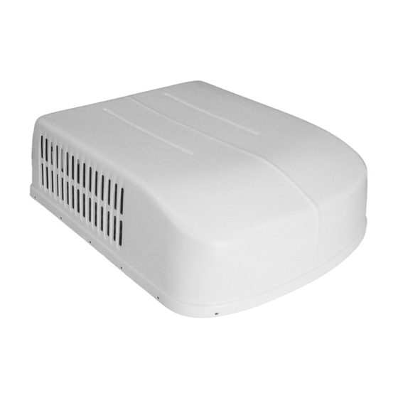
Duo-Therm 57915.522 Installations- und Betriebsanleitung - Seite 6
Blättern Sie online oder laden Sie pdf Installations- und Betriebsanleitung für Klimagerät Duo-Therm 57915.522 herunter. Duo-Therm 57915.522 17 Seiten. Roof top air conditioner/heat pump
Auch für Duo-Therm 57915.522: Installationsanleitung Handbuch (17 seiten)

The Installer of this air conditioner system must design the air distribution system for their particular application. Several
requirements for this system MUST be met for the air conditioner to operate properly. These requirements are as follows:
A. The duct material must meet or exceed any agency or RVIA Standard that may be in existence at the time the RV is produced.
B. All discharge air ducts must be properly insulated to prevent condensation from forming on their surfaces or adjacent surfaces
during operation of the air conditioner. This insulation must be R-7 minimum.
C. Ducts and their joints must be sealed to prevent condensation from forming on adjacent surfaces during operation of the air
conditioner.
D. Return air openings must have 40 square inches minimum free area including the filter.
E. Return air to the air conditioner must be filtered to prevent dirt accumulation on air conditioner cooling surface.
Return Air Cover Model
Roof Cavity Depth
Duct Cross Sectional Area
Duct Size
Depth
Width
Total Duct Length
Duct Length (short run)
Register Requirements
Number Required Per Run
Register Free Air Area
Distance From Duct End
Distance From Elbow
Duct Static
Blower at High Speed,
Filter & Grill In Place
Note: Duct sizes listed are inside dimensions.
** 12VDC Power supply is required.
4. AIR DISTRIBUTION SYSTEM
SIZING & DESIGN
CAUTION
It is the responsibility of the installer of in-
sure the ductwork will not collapse or bend
during and after the installation. Dometic
Corporation will not be liable for roof struc-
tural or ceiling damage due to improperly
insulated, sealed or collapsed ductwork.
AIR DISTRIBUTION
DUCT SIZING & DESIGN CHART
3105007.XXX
3105935.XXX
2.0 In. Min. - 5-1/2 In. Max.
21.0 Sq. In. Min.
1-1/2 In. Min. - 2-1/2 In. Max.
7.0 In. Min. - 10.0 In. Max.
15.0 Ft. Min. - 40.0 Ft. Max.
1/3 Total Duct Length
4 Min.
14.0 Sq. In.
5.0 In. Min. - 8.0 In. Max.
15.0 In.
0.55 - 0.90 In. W.C. 579 Series
0.40 - 1.10 In. W.C. 590, 591, 595 Series 0.40 - 1.10 In. W.C. 590, 591, 595 Series
0.12 - 0.65 In. W.C.
INSTALLATION INSTRUCTIONS DUCTED BI-METAL
6
**3308120.XXX
Genesis Air Filtration System
2.0 In. Min. - 5-1/2 In. Max.
32.0 Sq. In. Min.
2.0 In. Min. - 2-1/2 In. Max.
8.0 In. Min. - 10.0 In. Max.
15.0 Ft. Min. - 40.0 Ft. Max.
1/3 Total Duct Length
4 Min.
14.0 Sq. In.
5.0 In. Min. - 8.0 In. Max.
15.0 In.
0.55 - 0.90 In. W.C. 579 Series
0.12 - 0.65 In. W.C.
