Free The Tone PHA-1 Benutzerhandbuch - Seite 5
Blättern Sie online oder laden Sie pdf Benutzerhandbuch für Messgeräte Free The Tone PHA-1 herunter. Free The Tone PHA-1 12 Seiten. Phase analyzer
Auch für Free The Tone PHA-1: Benutzerhandbuch (6 seiten)
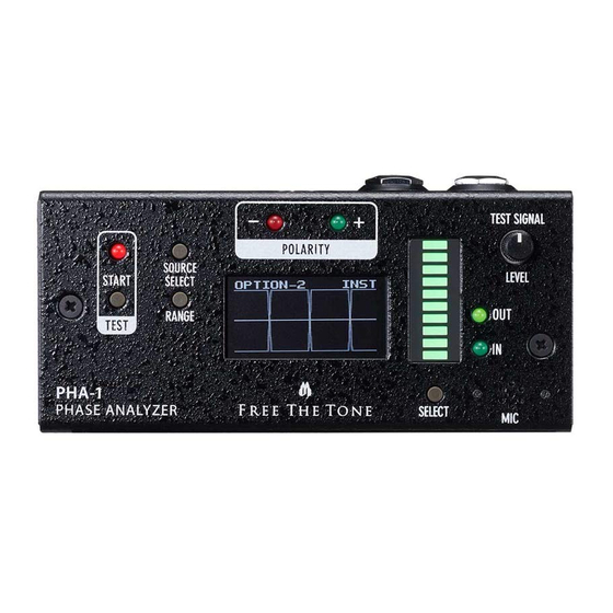
Basic Operation
Two Types of Phase Measurements and Phase Judgement Principle
The PHA-1 provides the two types of phase measurements.
< Repeated Pulse Measurement Mode >
In this measurement mode the PHA-1 outputs an in-phase test signal and judges the phase of the subject device by checking if the test
signal that goes through it is in phase or reversed phase. This mode can measure the phase of effects units such as a phaser, chorus, delay,
etc. in which delay elements are used, and devices that can cause a latency in the output due to AD/DA converters or DSPs used in them.
NOTE
To measure the phase of a delay or reverb's dry sound, set the effect sound to zero (minimum). To measure the phase of a delay effects unit's delay
sound, cut the dry sound (Kill Dry) and set the number of repeats of the delay sound to 1.
< Continuous Measurement Mode >
In this measurement mode the PHA-1 performs phase analysis by comparing its output test signal with the input waveform in the
same length of time. A 440-Hz or 220-Hz measurement signal can be selected in this mode. Due to characteristics of this device,
phase judgement may change according to test signal frequencies. Use the 440-Hz signal mainly for effects units for guitars and the
220-Hz signal mainly for effects units for basses.
N.B. In this measurement mode the PHA-1 cannot measure the phase of the effects units such as a phaser, chorus, delay, etc. in
which delay elements are used.
NOTE
Pulse waveforms are used as the test signal for the PHA-1's MIC input in order to minimize the influence from ambient noises. If the first edge of the test signal
waveform after passing through the device is rising, then it is judged as in phase (+). If falling, then it is out of phase (–).
If the waveform level is too low, the waveform edges cannot be detected. Conversely if it is too high, noises other than the test signal are too strong and
the edges cannot be detected precisely. Adjust the RANGE switch, TEST SIGNAL LEVEL knob, or the output level of the subject device so that 4 to 9 LEDs of
the level meter illuminate.
5