AEV MIRAGE MK III Handbuch - Seite 6
Blättern Sie online oder laden Sie pdf Handbuch für Computer Hardware AEV MIRAGE MK III herunter. AEV MIRAGE MK III 12 Seiten. Broadcast audio processor 3-band

1 2 3 4
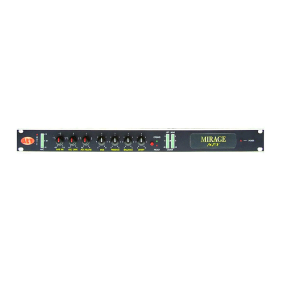
1. Led bar display for AGC control and led indicator for GATE status
2. Potentiometer for adjustment of AGC GATE THRESHOLD
3. AGC DRIVE adjustment potentiometer
4. AGC RELEASE adjustment potentiometer
5. BASS adjustment potentiometer
6. PRESENCE adjustment potentiometer
7. BRILLIANCE adjustment potentiometer
8. DENSITY adjustment potentiometer
9. OPERATE/BY-PASS switch and led indicator
10. Led bar display for channels output
11. Led indicator power On/Off
1
1. MAIN line input socket and power On/Off switch
2. PILOT SYNC OUT * 19 KHz output signal for synchronization of external systems
3. SCA signal level trimmer*
4. SCA signal input *
5. RDS signal level trimmer *
6. RDS signal input *
7. Trimmer for control of pilote phase *
8. MPX composite signal output level trimmer *
9. MPX composite signal output *
10. Left channel output
11. Left channel output signal level trimmer
12. Trimmer for control of Right channel output signal
13. Right channel output
14. 15-way connector for connection to LUXOR
15. Left channel input
16. Left channel adjustment trimmer
17. Set Dip-switch
18. Right channel adjustment trimmer
19. Right channel input
* PRESENT ONLY ON MIRAGE FM MPX
AEV Broadcast Srl via della Tecnica 33, 40050 Argelato Bologna ITALY
MIRAGE MK III - Broadcast Audio Processor
Command description
5 6 7
Front Panel
2
4
6
8
3
5
7
9
Rear Panel
www.aev.eu
8 9
10
10
12
11
13
11
14
16
18
15
17
19
6
