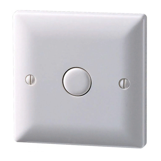
DANLERS TLSW 10 ILM Hinweise zur Installation - Seite 2
Blättern Sie online oder laden Sie pdf Hinweise zur Installation für Schalter DANLERS TLSW 10 ILM herunter. DANLERS TLSW 10 ILM 2 Seiten. Plated time lag switches (2-wire versions)

Installation procedure
1. Please read these notes carefully before commencing work.
In case of doubt please consult a qualified electrician.
Make sure the power is isolated from the circuit.
If a four lug metal back box is being used the top and bottom lugs
must be removed.
2. The TLSW 10 (ILM) has two terminal blocks on the reverse, which
should be connected as:
Block 1
L
Live input
SL
Switched Line output
Block 2
Push Button For connection to slave switch(es).†
Must not be connected to the mains.
3. Existing two-way strapper lines can usually be used to connect
these time lag switches in parallel or to connect slave switch(es),
as shown in the wiring diagrams opposite.
4 When these devices are wired in parallel, dependant on the load,
it may not be possible to immediately re-trigger the time lag.
5. The time lag is adjusted via a spindle (see
illustration opposite) by inserting a narrow
(flat) screwdriver through the hole located on
the bottom edge of the device:
Notes:
When wiring has been completed and verified, switch on supply, wait
for 30 seconds* and then test operation.
* If this is not observed, see trouble shooting section for remedy.
† The two terminals on DANLERS slave switches are labelled as:
Plated Slave switches:
Grid Slave switches:
If grid slave switches are used with plated time lag switches, the
L and S terminals must be connected only to the Push Button
terminals on the time lag switch, not to live.
APPROXIMATE
SETTINGS
5 mins
1
10
min
mins
TIME
Push Button
L, S
Typical wiring diagrams
1-way TLSW 10 (ILM)
TLSW 10 (ILM)
L
L
Push
Button
230 VAC
N
Example of a typical 2-way circuit
Multi-way TLSW 10 (ILM) with slave switches
SS 1SL
SS 1SL
Push button
Slave
Slave
Switch
Switch
Unused existing wire
terminate safely
Multi-way TLSW 10 (ILM) in parallel
L
SL
SL
L
TLSW 10
TLSW 10
(ILM)
(ILM)
Push button
Push button
Optional CAPLOAD(s)
Unused existing wire
See minimum load
terminate safely
SL
Optional CAPLOAD,
Power factor
load
correction capacitor.
See minimum load.
load
N
L
230 VAC
L
SL
TLSW 10
Push button
(ILM)
Optional CAPLOAD
load
See minimum load
N
L
230 VAC
L
SL
TLSW 10
(ILM)
Push button
load
N
L
230 VAC
