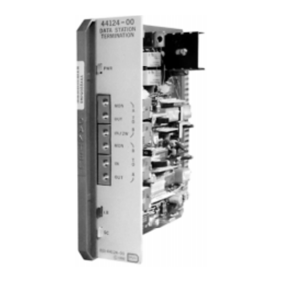
Dantel B11-44124-00 Handbuch für Installation und Betrieb - Seite 5
Blättern Sie online oder laden Sie pdf Handbuch für Installation und Betrieb für Kontrolleinheit Dantel B11-44124-00 herunter. Dantel B11-44124-00 16 Seiten. Data channel termination module

CIRCUIT DESCRIPTION
44124-0798 <90-00024>
Set signal amplitude (height or HT) with switches S7-1 to
S7-4. Each switch has an assigned value that determines the
total signal amplitude.
Set equalizer height (HT) with switches S7-5 to S7-8. Each
switch has an assigned value that determines the total band-
width.
You can bypass the input equalizer by setting switch S9 to BYP.
Input Amplifier
The input amplifier supplies up to 24 dB of gain or loss in
0.1 dB increments.
♦
Set the amplification level with switches S11-1 to S11-8.
♦
Set the amplification as a gain or loss with switch S13.
Loopback and Control Circuit
The loopback and control circuit breaks the drop side receive
and transmit paths, then connects the output of the receive path
to the input of the transmit path. The loopback and control
circuit is enabled in two ways. These are listed on the next page.
♦
The tone detector receives a 2713 Hz signal for at least
1.8 seconds. Tone detection provides remote testing of the
facility and its active components.
A guard circuit prevents signal frequencies near 2713 Hz
from enabling the loopback feature.
♦
Set switch S12-3 to ON, or connect pin 1 to pin 19 (ground).
Set loopback amplifier gain to 0, 8, or 16 dB with switches
S12-4 and S12-5.
When the loopback and control circuit activates, the TEK 5 and
6 connection leads open and relay K2 removes the sealing
current.
The loopback and control circuit is disabled in two ways:
♦
Set switch S12-2 to ON.
♦
The circuit times out after 4 or 20 minutes. Set switch
S12-1 to ON for a 4 minute timeout, and OFF for a
20 minute timeout.
At the end of the timeout cycle, relay K1 is released and the
loopback and control circuit is disabled. Receive and transmit
paths reset to normal. A second 2713 Hz tone also resets the
paths.
Output Amplifier
The output amplifier supplies up to 24 dB of gain or loss in
0.1 dB increments. Set the amplification level with switches S1
and S3. The amplified output signal couples to connector pins 41
and 47 and the XMT OUT jack contacts.
P
5
AGE
