Dantherm VA-M40 MKII Service-Handbuch - Seite 13
Blättern Sie online oder laden Sie pdf Service-Handbuch für Klimageräte Dantherm VA-M40 MKII herunter. Dantherm VA-M40 MKII 20 Seiten.
Combustion system
Introduction
This system consists of an oil burner , combustion chamber with heat exchanger ,
and the flue stack .
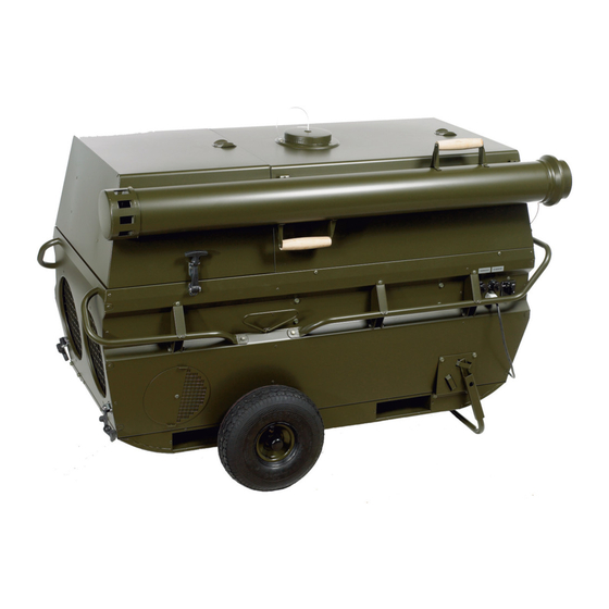
Illustration
This illustrates the combustion system:
Combustion sys-
This system consists of an oil burner , combustion chamber with heat exchanger ,
tem
and the flue stack .
The oil burner includes an electrically driven combustion air fan and a fuel pump, which
delivers diesel fuel to the nozzle where it is atomized. A certain mixture rate of com-
bustion air and atomized fuel will create a sort of gas which gives high efficiency com-
bustion without soot.
An electric transformer supplies high voltage for ignition across two electrodes upon
start up. When the flame is established the ignition ceases. The operation cycle is con-
trolled by a solid-state electronic device. During start up a 15 second pre-purge is fol-
lowed by the opening of the solenoid valve for oil atomizing and ignition. Safety shut-
down will occur after five seconds if a flame is not detected via the photo cell unit.
The burner flame is confined within a combustion chamber and heat exchanger of
sealed construction which prevents the combustion gases from escaping into the air cir-
culation system. The flame can be inspected through a small glass window in the
warm air discharge compartment.
An insulated flue stack is extended to discharge the exhaust gases upwards approxi-
mately 2 m above ground.
Fig. 2
No.
Part
Flue stack
Heat exchanger
Inspection glass
Oil burner
*
13