Dantherm NF-8HD Handbuch - Seite 17
Blättern Sie online oder laden Sie pdf Handbuch für Controller Dantherm NF-8HD herunter. Dantherm NF-8HD 20 Seiten.

01AUG 1005GB
LED "ON", is illuminated if the unit is in operation.
1.1
∆p
LED ">
-MIN" is illuminated if the differential pressure is higher than
1.2
∆p
LED ">
-MAX" is illuminated if the differential pressure is higher than
1.4
∆-button
2.4
M-button
2.5
∇-button
2.6
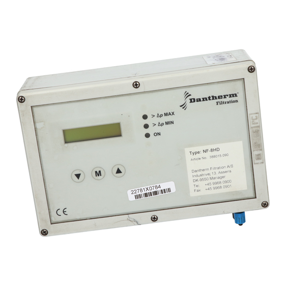
Fig. 1: LED's and buttons on the front of the controller
1
2
3
4
5
6
7
8
9 10 11 12 13 14 15 16 17 18 19 20 21 22 23 24 25 26 27 28 29 30 31 32 33
N PE A1 A2 A3 S1 S2 E1 E2 D1 D2 V1 + V2 + V3 + V4 + V5 + V6 + V7 + V8 + B1 B2 B3 B4
3.2
3.1
3.3
Power supply;1-3: 230 V AC, 2-3 110 V AC
3.1
Alarm relay, A1, A2, A3
3.2
Outfeeder in DTC operation, S1-S2
3.3
Down-time-cleaning E1-E2 (Fan start / stop signal inputs)
3.4
Start / Stop-input (external ∆p-switch)
3.5
Valve outputs; NF-8HD valves 1-8 ; NF-16HD valves 1-16
3.6
Data link to expansion units B1, B2, B3, B4
3.7
Data link to programming output signal (only NF-16HD)
3.8
Data link to Delta P external display 4-20 mA (only NF-8HD 4-20mA and NF-16HD)
3.9
Fig. 2:Terminals in the filter controller NF-8HD / NF-16HD
>
p MAX
>
p MIN
ON
34 35 36 37 38 39 40 41 42 43 44 45 46 47 48 49 50 51 52 53
S3 S4 V9 + V10 + V11 + V12 + V13 + V14 + V15 + V16 +
3.8
24V DC
. . . Ventile 2 bis 8
3.4
24V DC
3.5
Cat.20 / Tab. 05.91 / Page 07.04
1.1
1.2
1.3
2.1
2.2
2.3
. . . Ventile 10 bis 16
3.6
3.6
3.7
∆p
MIN.
∆p
-MAX.
_
+
F1 F2
3.9
