AudioStak ProSwitch PRSW-RCA-PCB Handbuch und Installationshandbuch - Seite 18
Blättern Sie online oder laden Sie pdf Handbuch und Installationshandbuch für Kontrolleinheit AudioStak ProSwitch PRSW-RCA-PCB herunter. AudioStak ProSwitch PRSW-RCA-PCB 20 Seiten.

COMM Bus Error Modes and Troubleshooting
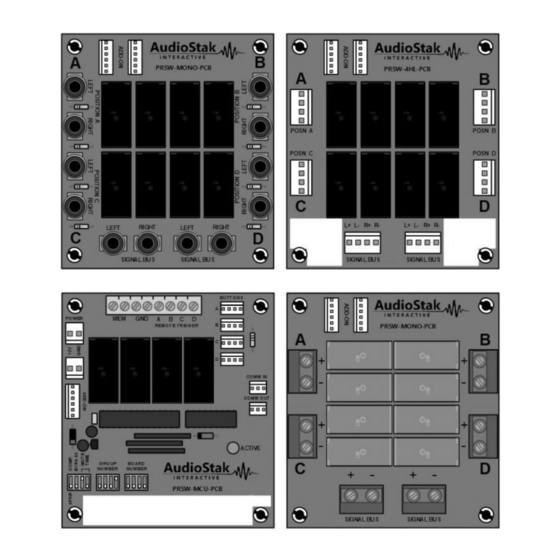
Main Module Active LED
Each time a button is pressed, the ProSwitch system checks the entire COMM Bus for proper operation. If there
is a COMM Bus wiring error anywhere in the system, the Active LED on each Main Module can blink in one of
three modes to assist in troubleshooting. This feature is designed to help the installer during initial wiring of a
ProSwitch system. The first step whenever there is a COMM Bus Error, signalled by one or more Main Modules
blinking their Active LED, is to ensure that all Main Modules in the system are properly receiving power.
Normal COMM Bus Communications
When a Main Module detects a button press, it communicates over its COMM Out connector to the COMM In
of the next Main Module. This data is passed from module to module until it passes through the complete
COMM Bus and returns to the module that initially sent it. In this way, the integrity of the COMM Bus wiring,
and the ProSwitch system as a whole, is validated each time a button is pressed. This is an important safety
feature of the ProSwitch system to help prevent the possibility of damage to connected components.
The COMM Bus consists of 2 wires. Pin 1 on each connector is DATA. Pin 2 on each connector is SYNCH. Data is
communicated over the DATA wire. The SYNCH line is used to alert modules that a communication is in
progress and then synchronize the actions of all modules in the system during switching events.
Note that even a system consisting of a single Main Module needs a COMM Bus cable connected between its
COMM In and COMM Out.
Timeout Error Mode
Active LED blinks slowly: one second on, one second off.
Cause of error
Initiation of a system communication was detected by this module on the SYNCH line, but no data was received.
Because this module did not receive data it will not be able to re-transmit it to the next module in the system,
so that module's Active LED will likely also be flashing in Timeout Error Mode. Modules that received and
retransmitted the data correctly will have their Active LED off.
Troubleshooting
Start with any module flashing in Timeout Error Mode. Follow the cable from its COMM In connector back to
the COMM Out on the previous Main Module in the system. If that board is also in Timeout Error Mode, repeat
until you reach a module with its Active LED off. This is the point in the system where the data failed to be
retransmitted correctly. The DATA wire on this cable is the most likely cause of the error. Another possible
cause is that this module is not receiving power. This could be caused by the Module Power Cable being
connected backwards or not plugged in properly.
Appendix H – COMM Bus Error Modes and Troubleshooting
