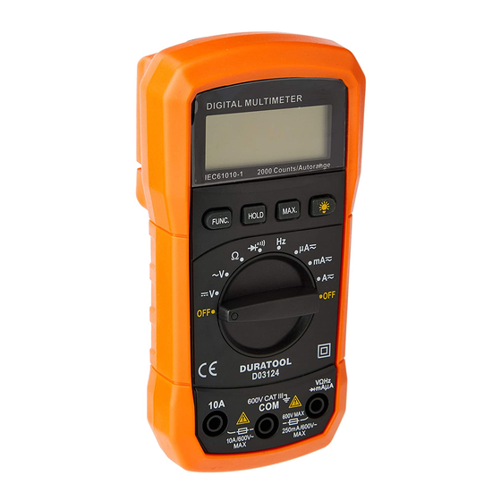
Duratool D03124 Handbuch - Seite 9
Blättern Sie online oder laden Sie pdf Handbuch für Multimeter Duratool D03124 herunter. Duratool D03124 10 Seiten. Digital multimeter autoranging
Auch für Duratool D03124: Schnellstart-Handbuch (9 seiten)

contact resistance value from the measured value.
•
For high-resistance measurement (>10MΩ), it is normal to take several seconds to
obtain a stable reading.
•
The LCD display will read "OL", indicating an open-circuit for the tested resistor or
the resistor value is higher than the maximum range of the meter.
DIODE CHECK
•
Set the rotary switch to the "
•
For the first time, the default mode is the diode check mode. You can enter the
continuity check mode by the "FUNC" key.
•
Insert the red test lead into the "VΩ" terminal and the black test lead into the
"COM" terminal.
•
Use the diode test mode to check diodes, transistors and other semiconductor
devices. In diode test mode, a current is sent through the semiconductor junction
and the voltage drop across the junction is measured.
•
A good silicon junction drop is between 0.5V and 0.8V.
•
For forward voltage drop readings on any semiconductor component, place the
red test lead on the component anode and the black test lead on the component
cathode. The measured value will be shown on the display.
•
Reverse the test lead and measure the voltage across the diode again.
- If the diode is good, the display shows "OL"
- If the diode is shorted, the display shows "0" (zero) in both directions.
- If the display shows "OL" in both directions, the diode is an open circuit.
CONTINUITY CHECK
•
Press the "FUNC" key to enter continuity mode.
•
The buzzer sounds if the resistance of a circuit under test is less than 100Ω.
FREQUENCY MEASUREMENT
•
Set the rotary switch to 'Hz' position.
•
Insert the red test lead into the VΩHz input terminal and the black test lead into the
COM terminal.
•
Connect the test leads across with the circuit under testing. The measured value
will be shown on the display.
Note: Input signal level must be higher than 0.5V.
DC/AC µA OR mA MEASUREMENT
•
DC current range is 200.0µA/2000µA and 20.00mA/200.0mA and then 10A range.
•
AC current range is 200.0µA/2000µA and 20.00mA/200.0mA and then 10A range.
•
Turn off power to the circuit and set the rotary switch to the proper DC/AC µA or
DC/AC mA position.
•
Break the current path to be tested. Connect the red test lead to the more positive
side of the break and the black test lead to the more negative side of the break.
•
Turn on the power to the circuit. The measured value will be shown on the display.
DC/AC 10A MEASUREMENT
•
Insert the red test lead into the input terminal marked as "10A".
•
Break the current path to be tested. Connect the red test lead to the more positive
side of the break and the black test lead to the more negative side of the break.
•
Turn on the power to the circuit. The measured value will be shown on the display.
Note: The measuring time for high current should be ≤10 seconds for each
" position.
9
