4B WDA3V34C Betriebshandbuch - Seite 15
Blättern Sie online oder laden Sie pdf Betriebshandbuch für Zubehör 4B WDA3V34C herunter. 4B WDA3V34C 20 Seiten. Wda sensor belt alignment / motion & broken / slack chain monitor

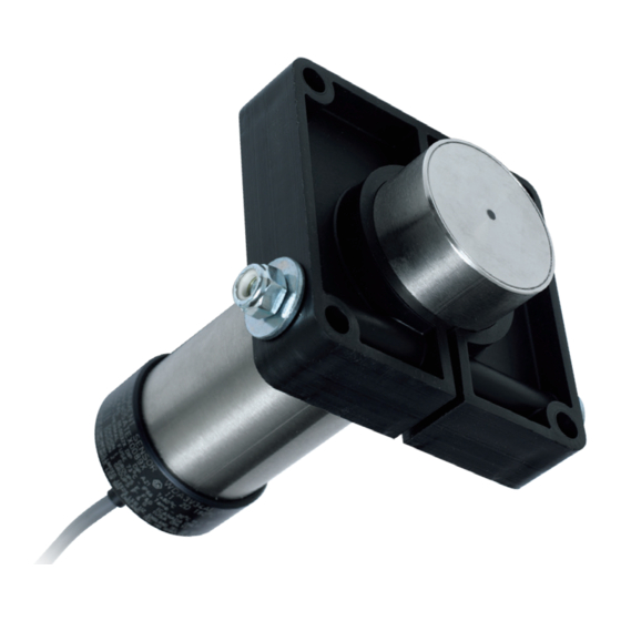
The sensor depth can be adjusted by loosening the adjustment bolt on the mounting bracket, sliding
the sensor to the required depth and retightening the bolt. Final sensitivity adjustments should be
made using the potentiometer sensing range adjustment screw.
Ensure that no ferrous steel, such as the machine's frame is within the target sensing field. This can
interfere with the sensor detecting the intended target.
All wiring must be In accordance with local and national electrical codes and should be undertaken by
an experienced and qualified electrician.
Always use dust/liquid tight flexible metal conduit with approved fittings to protect the sensor cables.
Use rigid metal conduit to protect the cables from the sensors to the control unit. Conduit systems can
channel water due to ingress and condensation directly to sensors and sensor connections which over
time will adversely affect the performance of the system. As such, the installation of low point conduit
drains is recommended for all sensors.
RED
BLACK
GREEN
YELLOW / ORANGE
BLUE
WHITE
To use the internal potentiometer within the WDA sensor, connect the YELLOW/ORANGE wire to the
RED wire. Turn the sensing range adjustment screw clockwise to increase the sensing range.
If using the A400 Elite Trackswitch control unit, follow the wiring instructions for YELLOW/ORANGE
wire as detailed in the A400 manual. Make sure to turn the sensing range adjustment screw on the
WDA sensor fully counter-clockwise when using the A400.
If using the Watchdog™ Elite control unit, connect the YELLOW/ORANGE wire to the RED wire.
Turn the sensing range adjustment screw clockwise to increase the sensing range.
UPDATING FROM DISCONTINUED WDA1 MODEL -
If you are updating from the older and discontinued WDA1 (plastic body) to the current WDA sensor
(stainless steel body), the wiring process is outline below:
WARNING
STANDARD WIRING DIAGRAM
+ Supply, 12 to 24 VDC ± 10%
- Supply, 0 VDC
Ground Connection
Control Signal 0 VDC to + VDC
Pulsed Output. Normally Low, High When Detecting
Continuous Output. Low when detecting, high when stopped for 2.5 seconds
WDA3
RED
BLACK
GREEN
YELLOW / ORANGE
BLUE
WHITE
NOTE
NOTE
WDA1
BROWN: +Supply VDC
BLUE: - Supply VDC
GREEN: Ground
----- Control
BLACK: Pulsed Output
----- Continuous Output
PAGE 15
