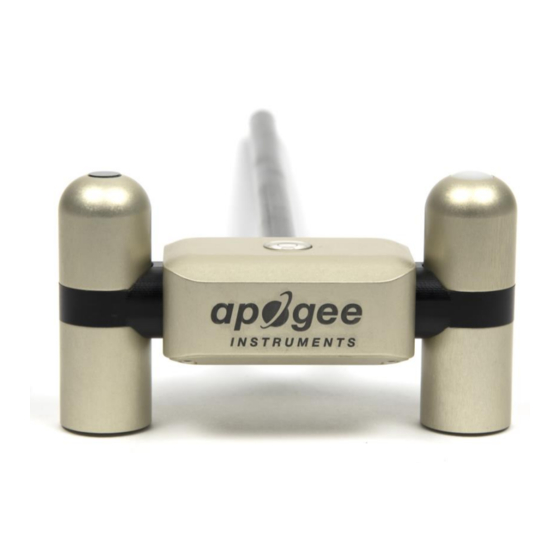
Apogee SN-500 Schnellstart-Handbuch - Seite 6
Blättern Sie online oder laden Sie pdf Schnellstart-Handbuch für Messgeräte Apogee SN-500 herunter. Apogee SN-500 6 Seiten. Net radiometer
Auch für Apogee SN-500: Benutzerhandbuch (19 seiten)

INSTALLATION
2.2 CONNECT TO METER ZENTRA SERIES LOGGER
Apogee net radiometers are preconfigured by METER and work seamlessly with METER
ZENTRA series data loggers. The sensors come with a 3.5-mm stereo plug connector
(Figure 2) to facilitate easy connection with the data loggers. Apogee sensors come standard
with a 5-m cable.
Figure 2 3.5-mm stereo plug connector wiring
Check the METER download webpage for the most recent data logger firmware. Logger
configuration may be done using either ZENTRA Utility (desktop and mobile application) or
ZENTRA Cloud (web-based application for cell-enabled ZENTRA data loggers).
1.
Plug the stereo plug connector into one of the sensor ports on the logger (Figure 3).
(+)
(-)
(-)
(+)
OK
ERROR
Port 1
Port 2
Port 3
Figure 3 Logger connection
2.
Connect to the data logger via ZENTRA Utility with a laptop and USB cable or ZENTRA
Utility Mobile app with a mobile device supporting Bluetooth
3.
Use ZENTRA Utility to scan the ports and make sure the sensors were properly identifi ed
by the logger and are reading properly.
METER data loggers should automatically recognize the Apogee sensor.
4.
Use ZENTRA Utility to set the measurement interval.
5.
Use ZENTRA Utility to confi gure communication settings for data transfer to ZENTRA Cloud.
Sensor data can be downloaded from METER data loggers using either ZENTRA Utility or
ZENTRA Cloud. Refer to the logger user manual for more information.
5
Ground
Digital communication
Power
(+)
(-)
(+)
(-)
(-)
(+)
(-)
(+)
TEST
Port 4
Port 5
Port 6
®
communication.
USING APOGEE NET RADIOMETERS WITH ZENTRA SYSTEM
3. DATA INTERPRETATION
Apogee net radiometers used with the ZENTRA system report the four individual components
and the combined net radiation in units of watts per square meter (W/m
combinations of the individual components (net short- and longwave radiation, albedo, etc.)
can be calculated during postprocessing, and some are included as environmental model
options in the ZENTRA Cloud reports page. Additionally, the sensor orientation information is
provided in the metadata tab of ZENTRA Cloud and ZENTRA Utility file downloads (Microsoft
Excel
®
spreadsheet) and on the measurement configuration page of ZENTRA Cloud. Sensor
orientation is reported as the sensor zenith angle in units of degrees, with a zenith angle of
0° indicating a sensor oriented straight up.
4. TROUBLESHOOTING
This troubleshooting section details possible major problems and their solutions. If the
problem is not listed or these solutions do not solve the issue, contact
Table 2 Troubleshooting
Problem
Possible Solution
Sensor not responding
Check power to the sensor and logger.
Check sensor cable and stereo plug connector integrity.
Check that the SDI-12 address of the sensor is 0 (factory default).
Check this with ZENTRA Utility by going to Actions, select Digital
sensor terminal, choose the port that sensor is on, and send the
?I! command to the sensor from the dropdown menu.
Sensor values are not reasonable
Verify the sensor is not shaded.
Verify the orientation angle of sensors.
Cable or stereo plug
If the stereo plug connector is damaged or needs to be replaced,
connector failure
contact
Customer Support
splice kit.
If a cable is damaged refer to the METER
cable repair.
It is recommended that Apogee net radiometers are returned for recalibration every 2 years.
Visit
Apogee repairs
(apogeeinstruments.com/recalibration-and-repairs) or contact
Technical Support
([email protected]) for details.
6
2
). Various other
®
Customer
Support.
for a replacement connector or
wire-splicing guide
for
Apogee
