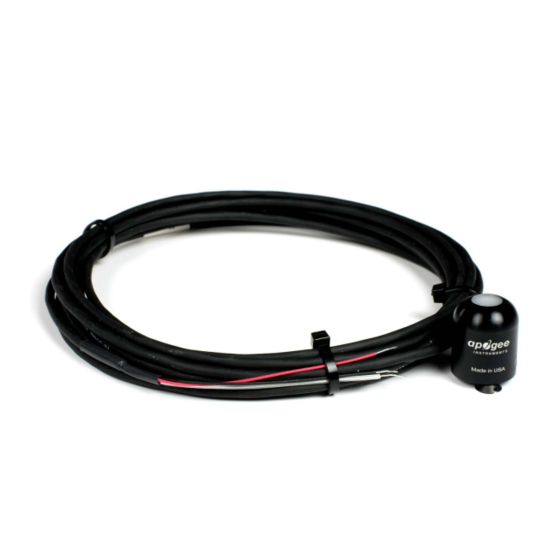
Apogee SP-215 Benutzerhandbuch - Seite 6
Blättern Sie online oder laden Sie pdf Benutzerhandbuch für Messgeräte Apogee SP-215 herunter. Apogee SP-215 19 Seiten. Pyranometer
Auch für Apogee SP-215: Benutzerhandbuch (18 seiten)

Power Supply
Current Draw
Sensitivity from serial numbers
10517 and above
Sensitivity from serial numbers
10516 and below
Calibration Factor from serial
numbers 10517 and above
Calibration Factor from serial
numbers 10516 and below
Calibration Uncertainty
Calibrated Output Range
Measurement Repeatability
Long-term Drift
(Non-stability)
Non-linearity from serial
numbers 10517 and above
Non-linearity from serial
numbers 10516 and below
Response Time
Field of View
Spectral Range
Directional (Cosine) Response
Temperature Response
Operating Environment
Dimensions
Serial # 12199 (SP-212),
12209 (SP-215) and above
Dimensions
Serial # 0-12198 (SP-212),
0-12208 (SP-215)
Mass (with 5 m cable)
Serial # 12199 (SP-212),
12209 (SP-215) and above
Mass (with 5 m cable)
Serial # 0-12198 (SP-212),
0-12208 (SP-215)
Cable
Calibration Traceability
Apogee Instruments SP series pyranometers are calibrated through side-by-side comparison to the mean of four
Apogee model SP-110 transfer standard pyranometers (shortwave radiation reference) under high intensity
discharge metal halide lamps. The transfer standard pyranometers are calibrated through side-by-side comparison
to the mean of at least two ISO-classified reference pyranometers under sunlight (clear sky conditions) in Logan,
Utah. Each of four ISO-classified reference pyranometers are recalibrated on an alternating year schedule (two
instruments each year) at the National Renewable Energy Laboratory (NREL) in Golden, Colorado. NREL reference
standards are calibrated to the World Radiometric Reference (WRR) in Davos, Switzerland.
SP-212-SS
5 to 24 V DC
nominal current draw 300 µA
1.25 mV per W m
2 mV per W m
-2
0.8 W m
per mV
0.5 W m
-2
per mV
± 5 % (see Calibration Traceability below)
0 to 2.5 V
maximum radiation measurement is 2000 W m
maximum radiation measurement is 1250 W m
360 to 1120 nm (wavelengths where response is 10 % of maximum;
± 5 % at 75° zenith angle (see Cosine Response below)
0.04 ± 0.04 % per C (see Temperature Response below)
-40 to 70 C; 0 to 100 % relative humidity; can be submerged in water up to 30 m
5 m of two conductor, shielded, twisted-pair wire; TPR jacket (high water resistance, high UV
stability, flexibility in cold conditions); pigtail lead wires; stainless steel (316), M8 connector
-2
-2
Less than 1 %
Less than 2 % per year
Less than 1 % (up to 2000 W m
Less than 1 % (up to 1250 W m
Less than 1 ms
180°
see Spectral Response below)
30.5 mm diameter, 37 mm height
24 mm diameter, 33 mm height
140 g
90 g
SP-215-SS
5.5 to 24 V DC**
**Sensors with a serial number smaller than 4502
should not be powered with more than 5 V DC
nominal current draw 300 µA
-2
2.5 mV per W m
4 mV per W m
-2
-2
0.4 W m
per mV
0.25 W m
-2
per mV
0 to 5 V
-2
;
-2
)
-2
;
-2
)
