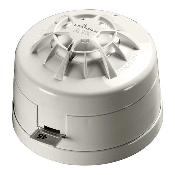
Apollo Xpander 29600-413 Handbuch für die Inbetriebnahme - Seite 5
Blättern Sie online oder laden Sie pdf Handbuch für die Inbetriebnahme für Sicherheitssensoren Apollo Xpander 29600-413 herunter. Apollo Xpander 29600-413 14 Seiten.

Installation
Installation should be done in accordance with the
radio survey and system design. Siting of the XPander
devices must be in strict accordance with the survey,
failure to do so may result in loss of performance.
Commissioning
When the system has been commissioned in accordance
with the instructions in this guide the XPander system
should communicate correctly. The completed site
survey document and this guide should be kept as
commissioning and user documentation to comply with
BS 5839-1, Section 2-27 and Sections 5-39 and 40.
After commissioning should the structure of the
building change a new site survey will be required along
with the completion of a new site survey document.
For ease of commissioning it is suggested that all
devices that are to be logged-on to a particular interface
are placed within easy reach of the interface. They can
be installed on their respective bases once the log-on
procedure for that interface has been completed.
Interface controls
Devices are logged-on to the system using the interface
controls. To access these controls it is necessary to
remove the front cover of the interface unit and access
the PCB.
Reset
868 MHz Aerial
Button
Connections
RADIO
TX
RX
RESET
Status
POWER
LEDs
FAULT
ISOLATE
WD
LOOP IN
-
LCD Contrast
Loop In, Out and
Adjustment
Screen Connections
Figure 1: Interface printed circuit board
Devices are logged-on to the system using the Rotary
Control as follows:
•
Turn the rotary control clockwise to scroll down
the menu shown on the LCD.
•
Turn the rotary control anti-clockwise to scroll up
the menu shown on the LCD.
8 Way loop
Front Lid
Tamper Switch
Address Switch
ON
1 2 3 4 5 6 7 8
1 2 3 4 5 6 7
0V
RX
HELP
TX
3V
Help
Button
Rotary
Control
Back
Button
BACK
LOOP OUT
-
LCD
Screen
•
Press the rotary control once to select the displayed
option.
Logging devices on to the system
Before devices can be logged-on to the system make
sure that the batteries are installed correctly and fit
the battery jumpers across both header pins as shown
below:
Detector
Sounder
MCP and RIM
Input/Output Unit
0
1
1
64
CLOSED
F-SAFE
LED
ENABLE
FAULT
INPUT 1 INPUT 2
Combined Sounder
and
Detector
Figure 2: Battery jumper and header pin positions
Note: The XPander Combined Sounder/Visual Indicator uses a DIL
switch to connect the battery supply.
PP2286/2019/Issue 13
Page 4 of 12
Requires
6 x AA batteries
Requires
3 x AA batteries
3 x C batteries
Requires
6 x AA batteries
Requires
6 x AA batteries
OUTPUT 1
OUTPUT 2
Requires
3 x AA batteries
3 x C batteries
