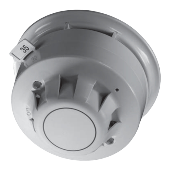
Apollo PP2209 Informationen zum Produkt - Seite 2
Blättern Sie online oder laden Sie pdf Informationen zum Produkt für Schiffsausrüstung Apollo PP2209 herunter. Apollo PP2209 4 Seiten. Integrated base sounder

TONE FREQUENCY AND VOLUME
CONTROL
The tone frequency of the sounders is pub-
lished in a separate document available for
Apollo Fire Detectors PP2203.
ADDRESSING
The integrated base sounder responds to its
own individual address set with a DIL switch.
It also responds both to a group address, set
by means of a 4-segment DIL switch and to a
pulsed-mode synchronisation address which
is em bed ded in the unit.
Addresses 1 to 111 are used exclusively for
in di vid u al addresses; addresses 112 to 126 are
used for group ad dress ing, while the synchro-
nisation address, to which all units respond,
is '0'. Any integrated base sounder on a
loop may be freely assigned to a group. The
address for any group must be chosen from
the range 112–126.
Addresses 112–126 may be used as individual
addresses but only if the 4-segment DIL switch
is not used ie,group addressing is disabled.
If the 4-segment DIL switch were set to any
number other than the default 127, a pre-set
analogue value of 4 would be transmitted to
indicate a fault.
The integrated base sounder is normally
polled by its individual address. It responds
as de scribed below (See PROTOCOL BIT
USAGE). If more than one integrated base
sounder is activated it is possible for the
sounders to be out of synchronisation with
the result that the signal in not clear.
To prevent this, it is recommended that the
synchronisation address '0' be sent by the
control panel at regular intervals to align the
internal clock of all sounders. The result is
that the sounders are synchronised with each
other in both 'alert' and 'evacuate' modes.
NB: Units on two or more loops can be syn-
chro nised only if the panel transmits address
'0' to all loops synchronously.
GROUP ADDRESSING
It may be desirable, in alarm conditions, to
switch more than one integrated base sounder
si mul ta ne ous ly. To enable this, sounders may
be controlled as a group and given a group
address which is common to all sounders in
the group. When a device recognises its group
address, it will proc ess the forward command
bits but it will not return any data to the
control panel on that ad dress. If it is re quired
to confi rm the status of the outputs of devices
under group address control, it is necessary
to interrogate all devices in the group at their
individual addresses.
SELF TEST
An important safety feature has been incorpo-
rated into the integrated base sounder: when
it is switched on it tests itself by checking the
actual sound output. If no sound is detected
within 5 seconds of the Integrated Base
Sounder being switched on it will transmit an
analogue value of 1 (= sounder fault) when it
is next polled.
This can also be used during commissioning
or periodical maintenance testing. Simply
activate the sounder for at least 5 seconds
and check the control panel for a fault signal.
If none is received, the sounder is working
properly.
PROTOCOL COMPATIBILITY
The sounder will operate only with control
equipment using the Apollo XP95 or Discovery
protocol. The features of the Integrated base
sounder are available only when the sounder
is connected to a control panel with the
ap pro pri ate software.
PROTOCOL BIT USAGE
The output (or forward command) bits from
the control panel have the following function:
Output bit 2 is used to apply the required
address mode — group addressing or indi-
vidual addressing.
Group addressing is selected by setting
output bit 2 of the individual address to
logic 0 on two or more consecutive cycles
and output bit 2 of the group address to
logic 1 on two or more consecutive poll-
ings. All other output bit 2 combinations
result in the application of the individual
address mode.
Whichever address mode — individual or
group — is applied in any polling, the use
of the other output bits is identical:
When output bit 1 is set to logic 1 on two or
more consecutive pollings, the 'alert' tone
is sounded.
When output bit 0 is set to logic 1 on two
or more consecutive pollings, the 'evacu-
ate' tone is sounded. The sounder will also
operate continuously if both output bit 1
and output bit 0 are set to logic 1 on two or
more consecutive pollings.
