Apollo Smoke Detector XP95 Installationshandbuch - Seite 8

Blättern Sie online oder laden Sie pdf Installationshandbuch für Sicherheitssystem Apollo Smoke Detector XP95 herunter. Apollo Smoke Detector XP95 18 Seiten. Input/output unit
Auch für Apollo Smoke Detector XP95: Installations- und Wartungshandbuch (4 seiten), Installationshandbuch (2 seiten), Installationshandbücher (2 seiten), Installationshandbuch (2 seiten), Schnellstart-Handbuch (2 seiten), Schnellstart-Handbuch (5 seiten), Installationshandbuch (2 seiten)
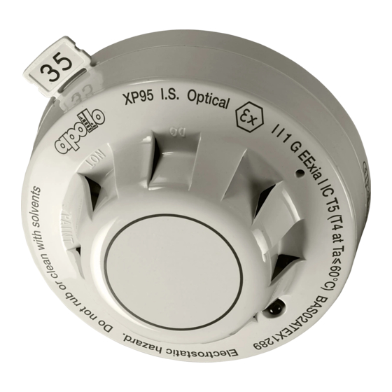
Apollo Smoke Detector XP95 Installationshandbuch

Installing transmitter and receiver

1. The XP95 beam detector is immune to most nor-
mal ambient lighting but the receiver should be so
installed that strong light sources–either sunlight
or artifi cial–do not project directly into the receiver
lens.
2. Locate the right-angle fi xing brackets for the trans-
mit ter and receiver so that they are on the line of
sight and are both installed approximately 0.3m
to 0.6m below the ceiling. The shorter leg of the
bracket is fi xed to the mounting surface as shown
in Fig 5.
Fig 5 Mounting bracket for beam detector
3. Fit the transmitter and receiver to the brackets using
the plastic insulating sleeves and washers provided
as shown in Fig 5. Align the receiver as ac cu rate ly
as possible to the transmitter by eye. Ensure that
the transmitter is fi tted so that access to the range
potentiometer (under the clear plug on the side) is
not impeded.
L1 L2
Black
Red
Junction box
(not supplied)
XP95/Discovery loop.
The transmitter can be
connected to any point
of the loop.
Fig 6a Connecting the transmitter to the loop
www.acornfiresecurity.com
4. Tighten both the receiver thumbwheel screws
securely, using a suitable coin or wide-bladed
screw driv er and ensure that all bracket fasteners,
eg, bolts, are secure.
5. Install all cables and connect as shown in Figs 6a
and 6b. (Transmitter and receiver are each sup-
plied with 1m of cable and this should be correctly
ter mi nat ed with the system wiring).
Fig 6b Connecting the receiver to the interface
8
www.acornfiresecurity.com
The receiver is
A B C D
connected to
the interface.
Colour
Terminal
Red
Black
Yellow
Blue
Junction
box (not
supplied)
A
B
C
D