APP 1309G2 Betriebs- und Wartungsanleitung
Blättern Sie online oder laden Sie pdf Betriebs- und Wartungsanleitung für Crimpwerkzeug APP 1309G2 herunter. APP 1309G2 2 Seiten. 1309 series
Auch für APP 1309G2: Anleitung für Betrieb und Wartung (2 seiten)
NOTE: Use of non– Anderson Power Products (APP) crimp tools can affect UL & CSA approval. See website
for comprehensive application tooling data and the most current versions of documents, including this one.
Operating Procedure
1.
Strip cable according to manufacturer's specifications.
2.
Select the appropriate cavity for the contact being crimped per below chart.
3.
Place contact on lower die with the contact wings or crimp barrel crease facing towards the
upper die (See Figure 1). Press the contact fully back into the locator until the wire stops or the
crimp barrel end is slightly inside the locator (See Figure 2).
4.
Close tool carefully until jaws grip the contact.
5.
Insert the properly stripped wire into the contact.
6.
Holding the wire in place, close the tool past the ratchet release position and allow the jaws
to open. (A ratchet release lever is provided to allow removal of an incorrectly placed or
oversized contact).
7.
Remove and inspect the crimp. There should not be any noticeable distortion in the angle of the
contact blade (See Figure 3).
8.
Test by holding contact and pulling firmly on cable.
Tooling
Part Number
Contacts
1309G1 *
1202G1
1203G1
1309G2
1331
1332
262G1-LPBK
200G2L-LPBK #16-20 (1.5-0.5)
269G2-LPBK
1309G3
261G1-LPBK
261G2-LPBK
261G2-LPBK
269G1-LPBK
269G3-LPBK
1309G4*
1307
5900
5914
5915
5952
903G1
904G1
1339G2
1339G3
1339G5
1309G5 / G6
200G1L-LPBK 6mm, #10-14
201G1H-LPBK 6mm, #10-14
1309G6
1830G1-LPBK 6mm, #10-14
1309G9
2003G1-LPBK #12 (4.0)
2003G1-LPBK #14, 16, 18 (2.5 - 1.5)
1309G10***
2003G2-LPBK #12 (4.0)
2003G2-LPBK #10 (60)
* No locator
** Anderson Power Products' (APP) crimp recommendations are only recommendations and are based on the
specific wire used by APP in APP specific testing. Wire will vary by type, material, class, and manufacturer's
rating & specifications. APP crimp recommendations are intended to be used as a guide towards achieving UL
& CSA compliant crimps that enable the best performance of our connector systems. It is incumbent upon those
assembling / manufacturing with APP connectors to perform pull-out strength, mV drop, and other testing as
needed to ensure that crimps meet the customer specific requirements.
*** Should only be used with 2003G2-LPBK contacts.
w w w . a n d e r s o n p o w e r . c o m
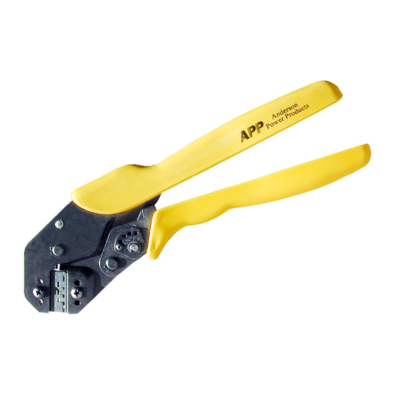
1309 Series Crimp Tool
Instructions for Operation & Maintenance
Wire Size
Pullout Values (lbs)**
AWG(mm²)
(per UL standard 486A)
#14-16 (2.5-1.5)
50-30
#14-16 (2.5-1.5)
50-30
#12-16 (4.0-1.5)
70-30
#16-20 (1.5-0.5)
30-13
#16-20 (1.5-0.5)
30-13
30-13
#16-20 (1.5-0.5)
30-13
#12-14-16 (4.0-2.5-1.5)
70-50-30
#14-16 (2.5-1.5)
50-30
#10-14 (6.0-2.5)
80-70
#12-16 (4.0-1.5)
70-30
#10-14 (6.0-2.5)
80-50
#6 (16.0)
100
#6 (16.0)
100
#10-12 (6.0-4.0)
80-70
#10-12 (6.0-4.0)
80-70
#8 (10.0)
90
#6 (16.0)
100
#10-12 (6.0-4.0)
80-70
#6 (16)
100
#10-12 (6-4)
80-70
#8 (10)
90
80, 80-50
80, 80-50
80, 80-50
70
50, 30, 20
70
80
Upper die
Locator
Lower die
Figure 1
*
Open Barrel Contact
End of locator
Tool Cavities
A
A
30
15
15
Correct
15
15
Closed Barrel Contact
A
A
End of locator
B
A
A
Large
Large
Small
Large
Large
Correct
Large
Large
Large
Figure 2
Large
Large
B
B
B
Large
Small
OK
Front
Rear
Figure 3
To far out
from locator
Not Correct
To far out from
locator
Not Correct
Wire stop
Nose up
Nose down