elsner elektronik 40115 Technische Daten und Installationsanweisungen - Seite 9
Blättern Sie online oder laden Sie pdf Technische Daten und Installationsanweisungen für Zubehör elsner elektronik 40115 herunter. elsner elektronik 40115 9 Seiten. Indoor sensor and ventilation control
2.3.5. Wiring diagram smoke and heat extraction system
Fig. 6
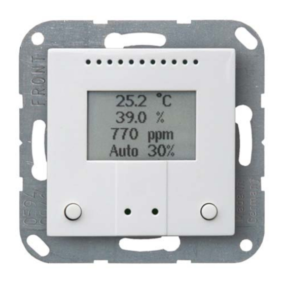
2.4. Sensor assembly
First, place the windproof box with the supply connection. Seal the inlet tubes, too, in
order to prevent drafts.
Then screw the base plate onto the junction box and position the frame of the switch
range on top of this. Connect the CO
connections.
Insert the sensor housing firmly into the metal frame using the catches, so that the
sensor and frame are fixed together.
2.5. Notes on mounting and commissioning
Never expose the device to water (e.g. rain) or dust. This can damage the electronics.
You must not exceed a relative humidity of 95%. Avoid condensation.
Ventilation Control AQS/TH PF • Version: 31.01.2017 • Technical changes and errors excepted.
Place the CO
sensor unit into the box. The side with the sensor
2
membrane must be facing the front.
Fig. 7
9
sensor unit, operating voltage and all other
2
Installation and start-up