elsner elektronik 60542 Technische Daten und Installationsanweisungen
Blättern Sie online oder laden Sie pdf Technische Daten und Installationsanweisungen für Controller elsner elektronik 60542 herunter. elsner elektronik 60542 2 Seiten. Radio motor control unit
EN
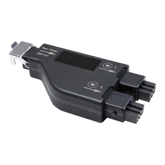
RF-MSG2-DST
Radio Motor Control Unit
Technical specifications and installation instructions
Item number 60542
1.
Description
The RF-MSG2-DST is a radio motor control unit for the controls WS1 and WS1000
Color or Style or the radio control Solexa II. Drives (e.g. shadings or windows) can
be connected to the control unit. A drive connected to the radio motor control unit
can also be operated directly using the remote controls Remo, via the push buttons
Corlo P RF or via the button interface RF-B2-UP (without an additional control unit).
The motor control unit RF-MSG2-DST has two drive outputs. These can be used to
connect drives for two shades, two windows, or one shade and one window, con-
trolled separately.
Functions:
•
Control of drives for shading (e.g. blinds) or windows
•
2 connections for 230V-drives
•
Reception of the radio control signal
•
Suitable for Controls WS1 Color, WS1 Style, WS1000 Color,
WS1000 Style (from software version 1.822), KNX WS1000 Style, Solexa II
(from software version 1.4), Radio remote controls Remo 8 and Remo pro,
button interface RF-B2-UP, push button Corlo P1 RF, push button Corlo P2 RF
1.0.1. Safety advice
WARNING!
Risk of injury caused by components moved automatically!
The radio transmission takes place over a non-exclusively available
transmission channel. If the radio connection between the control
system and the radio actuator is interrupted, connected devices can no
longer be operated!
•
Do not connect devices to the radio actuator that pose a danger
to people or material property
•
Devices with an increased risk of accident or high safety-related re
quirements must only be connected with additional safety devices
(e.g. an emergency stop device)
•
Observe the legal regulations governing the installation and
operation of radio systems
1.1. Deliverables
•
Radio motor control unit
•
Rubber seal
Additionally available:
•
Mains connection wire (5 m)
•
Connection wire (available in 1 m; 2,5 m; 5 m)
1.2. Technical Data
Housing
Plastic
Protection category
IP 53*
Dimensions
ca. 149 x 72 x 29 (W x H x D, mm)
Weight
ca. 203 g
Ambient temperature
Operation -25...+70 °C, storage -30...+85°C
Ambient humidity
max. 95% RH, avoid condensation
Operating voltage
230 V AC
Input
230 V AC, 50 Hz (Up/Down/N/PE)
STAS3 plug
Output
2 x drive (STAK3 coupling), 230 V AC (Up/Down/N/
PE), total load up to 4 A / 230 V AC
Radio frequency
868,2 MHz
*The Radio motor control unit RF-MSG2-DST should be installed in a protected
area despite a high protection category because water can enter in via the connec-
tors. Please observe the instructions in Chapter Connection.
The product conforms with the provisions of EU directives.
Radio motor control unit RF-MSG2-DST • Version: 09.06.2020 • Technical changes and errors excepted. • Elsner Elektronik GmbH • Sohlengrund 16 • 75395 Ostelsheim • Germany • www.elsner-elektronik.de • Technical Service: +49 (0) 7033 / 30945-250
Radio motor control unit RF-MSG2-DST
2.
Installation and start-up
2.1. Installation notes
Installation, testing, operational start-up and troubleshooting should
only be performed by an electrician.
DANGER!
Risk to life from live voltage (mains voltage)!
There are unprotected live components within the device.
•
VDE regulations and national regulations are to be followed.
•
Ensure that all lines to be assembled are free of voltage and take
precautions against accidental switching on.
•
Do not use the device if it is damaged.
•
Take the device or system out of service and secure it against
unintentional use, if it can be assumed, that risk-free operation is no
longer guaranteed.
The device is only to be used for the intended purpose described in this manual. Any
improper modification or failure to follow the operating instructions voids any and
all warranty and guarantee claims.
After unpacking the device, check it immediately for possible mechanical damage.
If it has been damaged in transport, inform the supplier immediately.
The device may only be used as a fixed-site installation; that means only when as-
sembled and after conclusion of all installation and operational start-up tasks and
only in the surroundings designated for it.
Elsner Elektronik is not liable for any changes in norms and standards which may
occur after publication of these operating instructions.
2.2. Notes on wireless equipment
When planning facilities with devices that communicate via radio, adequate radio
reception must be guaranteed. The range of wireless control will be limited by legal
regulation and structural circumstances. Avoid sources of interference and obsta-
cles between receiver and transmitter, that could disturb the wireless communica-
tion. Those would be for example:
•
Walls and ceilings (especially concrete and solar protection glazing).
•
Metal surfaces next to the wireless participants (e. g. aluminium construction
of a conservatory).
•
Other wireless devices and powerful local transmitters (e.g. wireless
headphones), which transmit on the same frequency. Please maintain a
minimum distance of 30 cm between wireless transmitters for that reason.
The antenna symbol on the housing shows the position
of the antenna in RF-MSG2-DST. This side must not
Metal
be positioned directly on metal surfaces or objects. Ot-
profile
herwise, the radio signal might disturbed.
2.3. Connection
The radio module is connected between the appliance and the power supply. It may
only be connected to flexible lines using STAK/STAS connectors. The connectors
must be locked using the locking bow. Use the provided rubber seals between the
STAK/STAS connectors. The connectors must be locked using the STASI locking
bow.
Up to 12 radio motor control units and a power load of up to 1.5 kW can be used per
mains connection.
Do not expose to continuous sun radiation to avoid overheating.
The housing is not UV-resistant.
No water may run along the supply line and device.
•
Assembly the device in a protected area (e. g. in
the box for the blinds/marquee/shutters in a construction
profile beneath the roof tiles or in a housing).
•
Lay the supply lines out and down from the device.
No vibrations!
•
Assemble the device in a place that is free of vibrations.
1