elsner elektronik 30114 Technische Daten und Installationsanweisungen - Seite 2
Blättern Sie online oder laden Sie pdf Technische Daten und Installationsanweisungen für Wetterstation elsner elektronik 30114 herunter. elsner elektronik 30114 2 Seiten.

Fig. 7
Different mounting arms are available
from Elsner Elektronik as additional, op-
tional accessories for flexible installation
of the weather station on a wall, pole or
beam.
Example of the use of a mounting arm:
Due to flexible ball joints, the sensor can
be brought into ideal position.
Fig. 8
Example use of the hinge arm mounting:
With the hinge arm mounting, the weat-
her station projects from beneath the
roof overhang. Sun, wind and precipita-
tion can act upon the sensors without
hindrance.
Fig. 9
Example use of the hinge arm mounting:
Fitting to a pole with worm drive hose
clips
2.3.1. Rear view and drill sketch
Fig. 10 a+b
Drill sketch.
Dimensions of the rear side of the hou-
sing with holder, dimensions in mm. Di-
vergences are possible for technical
reasons.
2.4. Preparation of the weather station
Unsnap cover and
remove upwards
Fig. 11
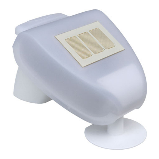
1 Cover with rain sensor
2 Cover snaps
3 Bottom part of housing
The weather station lid with the rain sensor latches into place on the lower edge to
the right and left. Remove the lid from the weather station. Proceed carefully to avo-
id tearing off the cable connection between the circuit board in the lower section and
the rain sensor in the lid (cable with plug).
Lead the connection cable through the rubber seal on the underside of the weather
station and connect it to the terminals provided.
The power supply cable to the weather station should be a maximum of 300 m long.
The connection is made with a standard, UV-resistant telephone cable (A-2Y(L)2Y
2x2x0.6 or A-2Y(L)2Y 2x2x0.8).
Weather Station P03i-GPS • Version: 06.08.2020 • Technical changes and errors excepted. • Elsner Elektronik GmbH • Sohlengrund 16 • 75395 Ostelsheim • Germany • www.elsner-elektronik.de • Technical Service: +49 (0) 7033 / 30945-250
Weather Station P03i-GPS
Oblong hole 7,5 x 5
1
2
3
2.5. Layout of the circuit board
2.5.1. Mounting the weather station
Close the housing by placing the lid on the lower section. The lid must lock into pla-
ce on the right and left with a distinct click.
Fastening
For removal purposes, the weather station can be pulled upwards against the resis-
tance of the notches.
3.
Installation notes for the weather station
Do not open the weather station when water (rain) can enter into it: Even a few drops
may damage the electronics.
During installation care must be taken that the temperature sensor (small plate on
the underside of the housing) is not damaged. The cable connection between the
plate and the rain sensor should also not be torn off or bent when being connected.
After installation, remove all transport protection stickers present.
The wind measurement can first be output about 30 seconds after applying the sup-
ply voltage.
3.1. Maintenance of the weather station
WARNING!
Risk of injury caused by components moved automatically!
The automatic control can start system components and place people in
danger (e.g. moving windows/awnings if a rain/wind alarm has been
triggered while cleaning).
•
Always isolate the device from the mains for servicing and cleaning.
The device must regularly be checked for dirt twice a year and cleaned if necessary.
In case of severe dirt, the sensor may not work properly anymore.
ATTENTION
The device can be damaged if water penetrates the housing.
•
Do not clean with high pressure cleaners or steam jets.
4.
Disposal
After use, the device must be disposed of or recycled in accordance with the legal
regulations. Do not dispose of it with the household waste!
Fig. 12
1 Slot for control unit/vol-
tage connection, 1: +24
V DC | 2: GND
terminal configuration
1
independent from pola-
2
rity
2 Cable connection to the
precipitation sensor in
3
the housing lid
3 GPS reception LED mo-
nitor
Fig. 13
Check that the lid and lower section
have properly latched into place! The
diagram shows the closed weather
station from below.
Fig. 14
Push the housing from above into the
fitted holder. In doing this, the studs in
the holder must click in to the tracks
on the housing.
2
