4M SMART ROBOT Handbuch - Seite 2
Blättern Sie online oder laden Sie pdf Handbuch für Robotik 4M SMART ROBOT herunter. 4M SMART ROBOT 2 Seiten.

D. ASSEMBLY
Follow these steps to assemble your Smart Robot. Numbers refer to the diagrams.
ASSEMBLING THE INSIDE MECHANISM
1. Identify the motor housing (it contains a switch and the battery case attached). Hold the housing so the switch is
facing down. Place the motor into the space in the housing.
2. Before lowering the motor into place, carefully feed the wires from the motor down through the holes in the
motor housing.
3. Find the smaller of the two axles with cogs. Drop the end with the larger of the two cogs into the white plastic
bearing hole close to the end of the worm gear. The lower cog should interlock with the worm gear.
4. Drop the metal end of the larger axle into the white bearing hole close to the corner of the motor. Its cog should
interlock with the top cog on the smaller axle. Apply some lubricant to the cogs. Cooking oil from the kitchen is
suitable.
5. Keep holding the motor housing upright so that the axles do not fall out. Carefully lower the motor housing cover
into place. You may need to slight wiggle it so that the tops ends of the axles fit into their upper bearings. If the cover
does not fit into place properly, remove it and make sure the axles and motor are still in their correct places.
6. Before screwing down the motor housing cover, slot the metal weight into place next to the battery case. It only
fits one way up. You'll have to lift the cover off the housing very slightly to do this.
7. Make sure the motor housing cover is in place properly and secure it with screws.
8. Connect the black wire from the battery case to one wire from the motor. Make connection to the shorter connec-
tion slot first (marked A). With the terminal cap, connect the black wire from the battery case to one wire from the
switch. After first pair of wires connected, connect together the remaining two wires (one from the switch and one
from the motor) at the taller connection slot (marked B). Then secure the two connection tabs with the long screw.
9. Insert an AA battery into the battery case. The negative terminal of each battery (the flat end) goes against one of
the springs in the battery case. If the motor runs, press the switch once to turn it off. Add the battery case cover and
secure it with a screw. Now test everything by pressing the switch. The motor should run and the white spindle should
turn. If the motor does not run, see the troubleshooting guide below. Press the switch to turn off the motor again.
1
2
7
3
4
8
A
1
B
6
A
B
9
ASSEMBLING THE SPHERE
10. Fit the soft plastic ring around the screw thread on the half sphere
without the hole in it.
11. Fit the motor assembly into the half sphere so that the white spindle
on the assembly fits into the square hole in the half sphere. Screw on the
other half of the sphere so that switch cover fits through the hole. Don't
5
over-tighten the screw thread.
4
FINAL ASSEMBLY
3
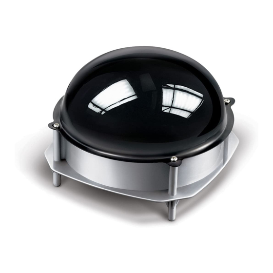
12. Put the top cover onto the base and secure it with four screws.
Congratulations. Your Smart Robot is ready to go!
E. OPERATION
2
Switch on the motor and push the sphere into the cover. Put the Smart Robot on a smooth surface (such as a vinyl
floor) and watch it go. Your Smart Robot does not run on carpeted flooring.
When it bumps into something, it automatically turns left or right and carries on going. Smart!
Try making a course using books for the Smart Robot to follow. You could even make a maze to see if the Smart
8
Robot can escape.
If you keep the sphere hidden when you show the Smart Robot to your friends, it will be a mystery to them how it
moves and steers itself.
11
10
12
