COOK Economizer Handbuch für Installation, Betrieb und Wartung - Seite 3
Blättern Sie online oder laden Sie pdf Handbuch für Installation, Betrieb und Wartung für Lüftungshaube COOK Economizer herunter. COOK Economizer 8 Seiten.
Type 2
Type 2
Type 1
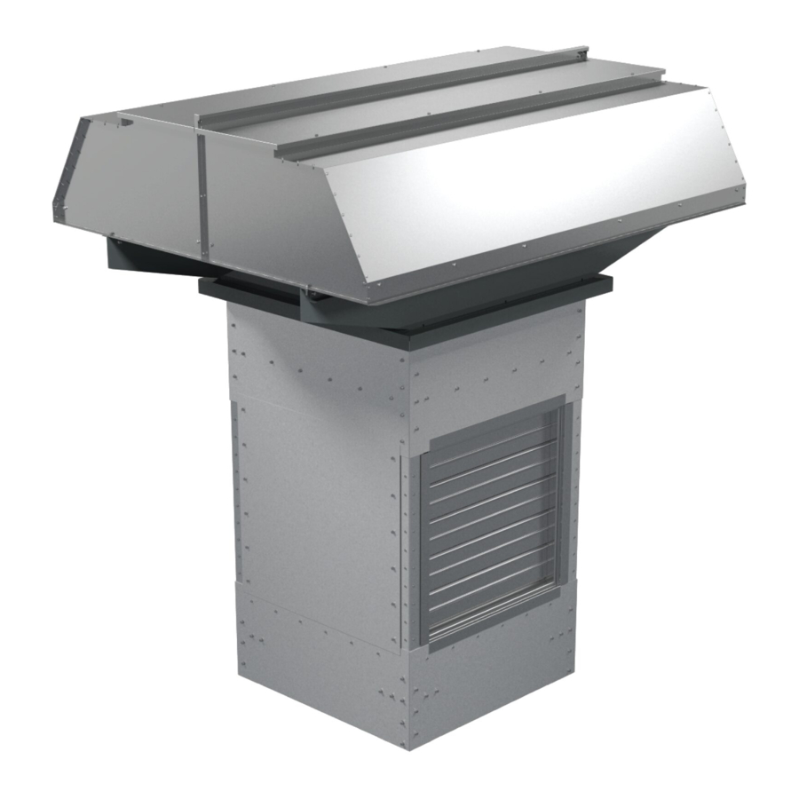
Economizer Fan
Type 1
Filter Schedule
Type 1
Type 2
Type 2
Follow the wiring diagram in the disconnect switch and the
wiring diagram provided with the motor.
Wiring Installation
All wiring should be in accordance with local ordinances
and the National Electrical Code, NFPA 70. Ensure the power
supply (voltage, frequency, and current carrying capacity of
wires) is in accordance with the motor name-plate. Refer to
the Control Panel Wiring Diagram, below.
Fan accessories will determine the wiring installation proce-
dure you should follow. If your unit has a disconnect switch,
ECONOMIZER IO&M
Type 2
Type 2
Type 2
Type 1
Type 1
Type 1
Type 2
Type 2
Type 2
Control Panel Wiring Diagram
follow the wiring diagram provided on the disconnect switch
and the wiring diagram on the motor.
Correctly label the circuit on the main power box and always
identify a closed switch to promote safety (i.e. red tape over a
closed switch).
Lock off all power sources before unit is wired to
power source. Restrain the wire as necessary to
pre-vent it from being pulled into any rotating parts.
Fan Wiring
Drill a wire access hole through the cabinet side below one
of the access doors. Attach the appropriate size wire and con-
duit to the motor and run the wires to the control panel. Attach
wires (18 gauge minimum) to the damper actuator (Red, Black,
#3) and the temperature sensor (Red, 2-White), if equipped,
and run the wires to the control panel. Attach the fan wires to
the control panel terminals according the diagram below.
Wire the roof disconnect switch, if equipped, and the fan
motor. The fan should rotate clockwise, when looking up from
the bottom, in supply mode. The rotation may be changed by
switching two of the three motor leads. When rotation is cor-
rect, reinstall the access panels.
3
B51132-003