austriamicrosystems AS1351 Anwendungshinweis - Seite 2
Blättern Sie online oder laden Sie pdf Anwendungshinweis für Hauptplatine austriamicrosystems AS1351 herunter. austriamicrosystems AS1351 5 Seiten. Programming board
AS1351
Programming Board Application Note
General Description
Switch Description
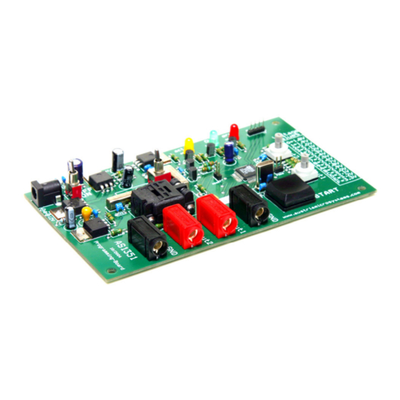
Figure 1: Board description
Table 1 : Switch description
Mark
Switch
Description
A
ON/OFF
ON/OFF switch
power
B
Voltage switch
supply
C
V
Programming voltage value 1
OUT1
D
V
Programming voltage value 2
OUT2
E
START
Start Button
Feedback and Socket Description
Table 2: Feedback and Socket Description
Mark
Name
Description
F
active
ON if Supply is active.
If ON after programming sequence,
the IC was successfully programmed.
G
OK
Blinks if an already programmed IC
was placed in the socket.
If ON after programming sequence,
H
error
the programming of the IC failed.
An AS1351 can be placed here, either
I
Socket
to be programmed or to be evaluated.
Input/Output Description
Table 3: Input/Output Description
Mark
Connector Description
Supply Voltage Connector (12V /
J
DC-Jack
900mA)
K-L
GND
Ground Pins
M
V
Output Voltage 1
OUT1
N
V
Output Voltage 2
OUT2
www.austriamicrosystems.com
Information
Board powered OFF
V
of the IC is set to 3.3V
CC
Rotary switch for programming V
values.
Rotary switch for programming V
values.
If hit the IC will be programmed with the chosen values for V
Figure 2: Board description
Revision 1.00
austriamicrosystems
Board powered ON
V
of the IC is set to 5V
CC
of the IC. Please see table for
OUT1
of the IC. Please see table for
OUT2
OUT1-2
2 - 4